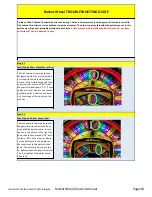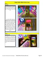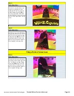
Step # 5
Wheel Speed Sensor
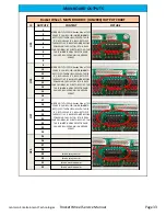
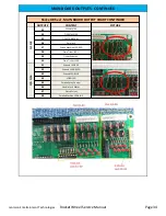
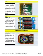
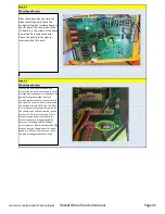
After checking coninuity across the
wheel interface board, check the
continuity from the interface board to
the I/O board. The connection to the
I/O board is in the middle of the board
on a white 5 pin molex connector.
Please see picture to the right for
location on the I/O board.
Step # 3
Wheel Speed Sensor
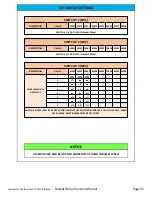
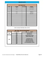
If all the connections mechanical and
eletrical are proper then we need to check
voltages from the sensor. In the back of the
game please grab voltages from the
cirsrlced molex connector in the picture to
the right. The sensor is a 5 volt sensor and
the positive line is the RED wire. The Black
wire is the common ground for the sensor.
You should see 5 volts accross the red and
black wires, 3.5 volts accross the Yellor /
Black wires and also across the White /
Black wires but the voltages should be
constant. That being said the Voltage
across the Blue / Black wires should be 3.80
when at rest and shoudl varry with wheel
speed to 3.90 volts. If this does not have
the proper voltages the sensor is bad.
Jennison Entertainment Technologies
Rocket Wheel Service Manual
Page 45


