background image

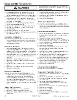
Disassembly Procedures

To avoid risk of electrical shock, personal injury or

death; disconnect power to unit before following any

disassembly procedures.

WARNING

!

20160

22217  Rev. 0

©2003 Maytag Appliances Company

9. Install sealed system access valve(s) and recover

refrigerant. After recovering, be sure to cap off the

access valve to prevent contamination of the system.

10.Remove the fan by removing the two nuts on the fan

mounting bracket at the baseplate. The fan wire

leads can be left connected. Set the fan assembly to

the side of the mechanical.

11. Remove the three nuts retaining the side of the fan

shroud. Remove the fan shroud.

12.Un-braze the capillary tube from the drier assembly.

13.Un-braze the hot gas valve tube at the tee on the

drier assembly.

14.Un-braze and remove the drier assembly.

15.Un-braze the hot gas line from the compressor at the

top of the condenser coil.

Condenser Installation:

Reverse the removal procedure. Be sure to evacuate to

50 microns before weight charging. If contamination

was found or determined, the evaporator should also

be replaced at this time.

Drain Valve Removal:

1. Drain water in the reservoir by removing the drain

plug or shutting off the water supply and allowing ice

maker to cycle through ice harvest cycle. Replace the

drain plug, if used, after the water has been drained.

2. Disconnect power, water line, and drain line. If a drain

pump is used, it will need to be disconnected and

removed.

3. Remove the access panel and rear panel.

4. Remove the brown and white wire terminals at the

drain valve.

5. Loosen the hose clamps on each side of the drain

valve .

6. Remove the two screws securing the drain valve.

7. Remove the drain valve.

Drain Valve Installation:

Reverse the removal procedure for installation. It is

important to keep the valve clean during installation

to assure proper performance. After installation,

make certain the hose clamps are secure and that

the valve or the tubing does not leak. This can be

done by adding water to the reservoir and observing

for any leaks from the tubing connections or the valve

itself.

 Water Valve Removal:

1. Disconnect power, water line, and drain line.

2. Remove the access panel and rear panel.

3. Remove the blue and white wire terminals at the

water valve.

4. Loosen the reservoir water supply line compression

nut from the bottom of the water valve.

5. Remove the two screws securing the water valve to

the unit’s support pan.

6. Remove the water valve.

 Water Valve Installation:

Reverse the removal procedure for installation. Make

certain that the reservoir waterline is in the reservoir

inside the unit and there are no water leaks anywhere

after installation.

Condenser Fan Removal:

1. Disconnect power, water line, and drain line. If a drain

pump is used, it will need to be disconnected and

removed.

2. Remove the access panel and rear panel.

3. Remove the grille by removing the two screws and

disconnecting the three wires to the rocker switch. Be

sure to mark where these wires go for re-assembly.

4. Remove the drain valve.

5. Remove the water valve.

6. Take out the two screws that secure the top of the

electrical bracket located in the front of the

mechanical area.

7. Remove the six screws that secure the baseplate to

the cabinet on the bottom of the unit.

8. Gently slide the mechanical out the rear of the unit

enough to gain access to the condenser fan.

9. Remove the two nuts that secure the condenser fan.

10.Disconnect the neutral white wire lead (black ribbed

wire) at the terminal block and the hot wire lead

(black smooth wire) at the electronic control.

11. Remove the condenser fan.

Condenser Fan Installation:

Reverse the removal procedure for installation.

 Evaporator Thermistor Removal:

1. Remove any ice and drain the reservoir by pulling the

drain plug.

2. Disconnect power, water line, and drain line.

3. Remove the access panel and rear panel from the

rear of the unit.

4. Disconnect the red and black wires to the

“EVAPORATOR THERMISTOR” terminals on the

electronic control.

5. From inside the unit, remove the escutcheon panel.

6. Remove the grid-cutter.

7. Remove the ice deflector.

8. Remove the reservoir.

9. Remove the evaporator thermistor by removing the

screw securing it.

Содержание JIM1550ARB

Страница 1: ...manual includes but is not limited to the following Jenn Air JIM1550ARB JIM1550ARW JIM1550ARS JIM1550ACX Service This manual is to be used by qualified appliance technicians only Maytag does not assu...

Страница 2: ...ING REPAIRS WARNING To avoid risk of severe personal injury or death disconnect power before working servicing on appliance to avoid electrical shock To locate an authorized servicer please consult yo...

Страница 3: ...tter Transformer 13 Grid Cutter 13 Reservoir 13 Circulation Pump 13 Troubleshooting 14 17 Disassembly Procedures Hot Gas Valve Removal 18 Hot Gas Valve Installation 18 Replacing the Evaporator 18 Comp...

Страница 4: ...identifications of individual units state complete serial number model and type This information is found on the serial plate located on front upper right hand corner of foodliner or on some models e...

Страница 5: ...loaded weight of the unit Refer toAppendix A owner s guide for additional information Electrical Requirements 115 VAC 60 Hz single phase power is needed Use outlet with a 15 amp delayed action fuse or...

Страница 6: ...ble tubing or poor ice production will result If installing a standoff gravity drain use Illustration below for location Standpipe can be up to 3 inches high above the floor Route tubing from ice make...

Страница 7: ...d for the first 35 minutes into the production cycle If during any production cycle or harvest cycle the selector switch is put into the CLEAN position any cycle in process will be immediately termina...

Страница 8: ...ch is moved from the CLEAN position all loads except the drain solenoid will de energize this includes the OFF position The drain solenoid will energize for 75 seconds and then de energize The unit wi...

Страница 9: ...in the system at the evaporator low side suction return line or accumulator If a leak is found in any of these areas moisture has probably entered the system The compressor drier and hot gas valve wil...

Страница 10: ...m with dry nitrogen gas and evacuate to 50 microns before re charging The method for recharging the unit is by weight using vapor refrigerant Using manifold gauge setup hook up charge hoses to the acc...

Страница 11: ...essor The compressor is the heart of the refrigeration system It also however relies on other parts of the system to function Make certain that the other parts of the system are correctly functioning...

Страница 12: ...e flow rate of the reservoir water line Using a stopwatch or a watch with a second hand see what amount of time it takes to fill up a one quart container The time should be 60 seconds to get the 25 gp...

Страница 13: ...d side of the transformer and reading the 12V side using a multimeter If no readout is found or readout is below 10VAC replace the transformer Grid Cutter The grid cutter is used to cut cubes from the...

Страница 14: ...for proper operation Distributor tube is restricted or not installed correctly See CLEANING YOUR ICE MACHINE section for cleaning the unit for proper operation Grid cutter is unplugged Plug in the gr...

Страница 15: ...o kinks or restrictions in the drain lines If using a drain pump check the inlet screen discharge line and vent line for any build or restrictions Leaking drain valve See CLEANING YOUR ICE MACHINE sec...

Страница 16: ...t for proper operation Build up of deposits on evaporator plate See CLEANING YOUR ICE MACHINE section for cleaning the unit for proper operation Inadequate drain system Restriction in drain lines will...

Страница 17: ...o side and front to rear Room temperature is too cold Move the unit to an area where temperature is above 55 deg F The selector switch is not in the ON position Set the rocker switch on the grille of...

Страница 18: ...itrogen gas and a leak detection system 9 Flush the system and recharge 10 Reassemble reversing steps 1 through 10 Replacing the Evaporator 1 Disconnect power water line and drain line If a drain pump...

Страница 19: ...ll need to disconnect the three wires from the old PTC starter and then connect the new one 12 Un braze and remove the capillary tube from the drier assembly 13 Un braze the tube from the hot gas valv...

Страница 20: ...r to the reservoir and observing for any leaks from the tubing connections or the valve itself Water Valve Removal 1 Disconnect power water line and drain line 2 Remove the access panel and rear panel...

Страница 21: ...the hot gas valve solenoid coil by removing the spring retainer rotating the coil 90 degrees and then lifting up 7 Take out the two screws that secure the top of the electrical bracket located in the...

Страница 22: ...1 Disconnect power to the icemaker 2 From inside the unit remove the escutcheon panel 3 Remove the grid cutter 4 Remove the ice deflector 5 Remove the reservoir 6 Unplug the circulation pump at the re...

Страница 23: ...23 BLACK RIBBED NEUTRAL OV LD COMPRESSOR GRID CUTTER TRANSFORMER THERMISTOR THERMISTOR EVAPORATOR THERMISTOR THERMISTOR SOLENOID BIN CLEAN GRID SOLENOID SOLENOID DRAIN WATER HOT GAS CUTTER FAN CONDEN...

Страница 24: ...2003 Maytag Appliances Company 16022217 Rev 0 A 1 Appendix A...

Страница 25: ...Introduction 2 Safety 3 Installation 4 9 Operation 10 Care and Cleaning 11 12 Before Calling for Service 13 18 Warranty 20 Guide du Propri taire 21 Gu a del Propietario 41 OWNER S GUIDE 41007621 4100...

Страница 26: ...need future assistance with your ice maker a complete model and serial number recorded in the spaces below will be extremely helpful These numbers are found on the data plate inside on the lower front...

Страница 27: ...apors and liquids Children should not climb hang or stand on or in this refrigeration product Read and follow manufacturer s warnings on ice machine cleaner products Personal injury can result when us...

Страница 28: ...rs Ideal Ambient Temperature Range Built In 55 80 F NOTE Ice maker will not perform correctly in ambient temperatures less than 55 F Cabinet Clearance The ice maker may be enclosed on the sides rear a...

Страница 29: ...nstallation WARNING The ice maker should remain upright at least 30 minutes prior to plugging it in CAUTION Level the Ice Maker Using a carpenter s level check to be sure the ice maker is level from s...

Страница 30: ...drain is not accessible NOTE Avoid kinks and check for proper water drainage after ice maker installation OBSERVE AND FOLLOW ALL LOCAL CODES WHEN INSTALLING ICE MAKER Failure to use adequate drainage...

Страница 31: ...a shut off valve between the ice maker and the water supply The shut off should be a drilled saddle valve Do not use a self tapping valve The valve should be installed in a vertical water pipe NOTE If...

Страница 32: ...ness maximum 1 Turn off the ice maker and disconnect the power 2 Remove 1 8 set screw A from the top hinge Remove the door off of the lower hinge noting washer location 3 Remove the door seal B to exp...

Страница 33: ...m wood panel and tighten 6 Reinstall the door seal by pressing it into the door channel Making certain the corners are fully inserted 7 Install the door back on to the ice maker using the supplied pla...

Страница 34: ...electronic control switches to the harvest cycle to harvest the ice slab During the harvest cycle the ice slab falls from the evaporator to the ice grid cutter Here the ice slab is cut into 3 4 square...

Страница 35: ...r panel and close door 7 Switch selector switch on the grill of the machine to the CLEAN position Three quarts of water will automatically be added to ice maker cleaner 8 The total cleaning time will...

Страница 36: ...eansers bleach or cleaners containing bleach These products can scratch and erode the paint finish DO NOT wax plastic or vinyl parts Use a soft cloth or sponge Always wipe with the grain of the stainl...

Страница 37: ...proper ice quality production and unit life 6 If ice maker is to be left unattended for a month or longer turn off its water supply switch the control to OFF and disconnect the power supply Remove an...

Страница 38: ...cycle can take up to 11 2 hours Initial startup cycles can be longer The selector switch is in the OFF or CLEAN position No water in the reservoir Distributor tube is restricted Build up of deposits o...

Страница 39: ...discharge line and vent line for any buildup or restrictions Remove the front cover panel and plug the grid cutter into the receptacle on the side of the liner Ice is slowly melting on the ice bin an...

Страница 40: ...nit to make sure there are no restrictions or kinks in the line Check all filters to make sure they are not restricted or plugged Make sure that the reservoir drain plug is installed properly Check th...

Страница 41: ...and front to rear Set the rocker switch on the grille of the ice machine to the ON position Remove the front cover panel and plug the grid cutter into the receptacle on the side of the liner It can ta...

Страница 42: ...nks or restrictions in the drain lines If necessary consult a qualified plumber Foreign material is restricting or blocking the ice bin drain located at the right rear corner of the ice bin The drain...

Страница 43: ...19 Notes 41007621 JA Ice Maker ENG 4 28 03 2 18 PM Page 19...

Страница 44: ...vicer 6 Consequential or incidental damages sustained by any person as a result of any breach of these warranties Some states do not allow the exclusion or limitation of consequential or incidental da...

Отзывы: