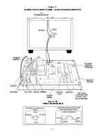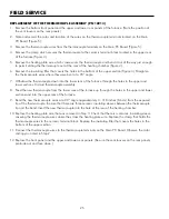
1 . . Remove .the .front .panel .(Figure .5) .
2 . . Note .and .record .the .color .and .location .of .each .wire .on .the .thermocouple .terminals .located .on .the .Main
.
PC .Board . .Remove .both .wires .
3 . . Remove .the .calibration .jack .connector .(J1) .from .the .Main .PC .Board .by .pulling .straight .up .
4 . . Remove .five .electrical .connectors .(BLACK, .ORANGE, .YELLOW, .WHITE, .GREEN) .from .the .Main .PC .Board .by
.
pulling .straight .up .on .the .connector . .DO .NOT .PULL .ON .THE .WIRES .
5 . . Remove .the .nuts .and .lockwashers .that .hold .the .Main .PC .Board .to .the .front .panel .and .lift .straight .up .to
.
remove .board .
.
6 . . Align .the .holes .in .the .new .board .with .the .standoffs .on .the .front .panel, .reinstall .the .fasteners .and .screws .
7 . . Reconnect .the .electrical .connectors .as .follows:
.
Black .wire .to .terminal .marked .“H .” . .- .E5 .
.
Orange .wire .to .terminal .marked .“GATE .” . .- .E4 .
.
Yellow .wire .to .terminal .marked .“LOAD .” . .- .E3 .
.
White .wire .to .terminal .marked .“N .” . .- .E2 .
.
Green .wire .to .ground .terminal . . .- .E1 .
8 . . Reconnect .calibration .jack .connector . .The .green .wire .on .the .connector .is .closest .to .the .bottom .edge .of .the
.
front .panel . .
9 . . Reconnect .the .two .thermocouple .wires .to .the .thermocouple .terminals .observing .the .color .coding .noted .in . .
.
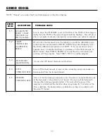
Step .2 . .If .thermocouple .wires .are .reversed, .5 .minutes .after .heating .program .is .started, ."Er .5" .will .appear
. . on .the .Main .Display .
10 . .Replace .the .front .panel .
FIELD SERVICE
REPLACEMENT OF THE MAIN PC BOARD
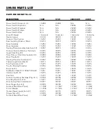
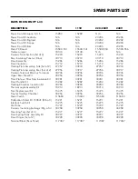
REPLACEMENT .PART .NUMBERS
23
100V
115V
220/230V
240V
M-30
15500-031 .
15500-041 .
15500-053 .
15500-056
L-30
15500-531 .
15500-541 .
15500-553 .
15500-556

