manualshive.com logo in svg
background image

SUN ODYSSEY 50DS

OWNER'S MANUAL

C

R

O

IS

IE

R

E

134949
Index K

Содержание SUN ODYSSEY 50DS

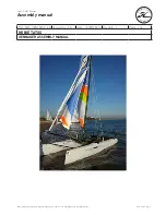
Страница 1: ...SUN ODYSSEY 50DS OWNER S MANUAL C ROISIERE 134949 Index K...

Страница 2: ......

Страница 3: ...complished sailor Even when your boat has been adapted for them the sea and wind conditions corresponding to the design categories A B C and D may vary ranging from severe conditions to strong storms...

Страница 4: ......

Страница 5: ...e navigation Always adapt the speed and direction of your boat to the conditions of the sea The boat shall not be loaded more with than the maximum load recommended by the builder in particular the to...

Страница 6: ...ey may be modified without prior notice or up dates This owner s manual is designed in accordance with the ISO 10240 standard requirements it has a general purpose and it may sometimes list some equip...

Страница 7: ...OF UPDATES Index A 02 2008 Index B Page 8 9 62 07 2008 Index C Page 8 48 52 10 2008 Index D 10 2009 Index E 09 2010 Index F 03 2011 Index G 05 2011 Index H 10 2011 Index I 08 2012 Index J 05 2013 Ind...

Страница 8: ......

Страница 9: ...ERING SYSTEM Page 45 Chapter 6 RIGGING AND SAILS Page 49 Chapter 7 INTERIOR Page 63 Chapter 8 WATER AND SEWAGE WATER Page 69 Chapter 9 ELECTRICAL EQUIPMENT Page 81 Chapter 10 ENGINE Page 111 Chapter 1...

Страница 10: ......

Страница 11: ...7 152 SPECIFICATIONS AND WARRANTY TECHNICAL SPECIFICATIONS CERTIFICATION DESIGN CATEGORY YOUR BOAT 1...

Страница 12: ...keel 17 958 kg Maximum load recommended by the builder 4 208 kg Including the mass of the persons who are authorized on board 75 kg 165 lbs per adult the supplies the liquids that can be used fresh wa...

Страница 13: ...e moyen principal de propulsion du SUN ODYSSEY 50DS CE Category Persons Maximum A 10 persons B 12 persons C 14 persons D 14 persons Design category Wind force Beaufort scale Significant height of wave...

Страница 14: ...hts significant wave height up to 2 m see Note 1 below You may meet with such conditions in exposed inland waters in estuaries and in coastal waters with moderate weather conditions Category D In shel...

Страница 15: ...TRATION NUMBER DELIVERY DATE DOOR KEY NUMBER MAKE OF ENGINE ENGINE SERIAL NUMBER ENGINE KEY NUMBER JEANNEAU Establishment of the company SPBI BP 529 85505 LES HERBIERS cedex FRANCE Tel 33 02 51 64 20...

Страница 16: ......

Страница 17: ...13 152 SAFETY SAFETY EQUIPMENT GENERAL INFORMATION GAS SYSTEM RECOMMENDATIONS FOR GAS FIGHT AGAINST FIRE BILGE PUMP SYSTEM EMERGENCY TILLER 2...

Страница 18: ...2 SAFETY EQUIPMENT Swimming ladder means of coming back onboard Reference 1 Liferaft not supplied Reference 2 Liferaft in the aft quarterdeck locker Note If over 10 persons on board 2 liferafts compul...

Страница 19: ...the ladder is in place and deployed as soon as you are on board Reduce speed in waves WARNING Before you sail list the compulsory safety equipment Don t exceed the number of persons indicated in the c...

Страница 20: ...16 152 GAS SYSTEM LOCATION Gas Vent hole REF Designation 1 Gas cylinder locker 2 Gas kill valve on bottle 3 Gas pipe 4 Gas rubber tubing 5 Tap to turn off the gas 7 Gas vent...

Страница 21: ...other layouts Opening valve Reheating gas closing Reference 1 A pictogram helps to locate it easily Valve REF Designation 1 Valve on appliance 2 Valve on cylinder 6 Open valve 7 Closed valve 2 Gas cy...

Страница 22: ...SYSTEM EUROPE VERSION REF Designation 1 Regulator valve 2 Gas cylinder 3 Drain 4 Connection kit gas bottle 5 Rubber washers 6 Pictogram 7 Connection kit gas copper 8 PVC girdled sleeve 9 Gas appliance...

Страница 23: ...to detect any gas leak Check all the connections using water and soap or detergent closing the valves of the appliances and opening the valve on the cylinder If you detect a leak close the valve of th...

Страница 24: ...rubber tubings that link the cylinder to one end of the circuit and the stove to the other one depending on the norms and regulations in force in your country Pay particular attention to keep in good...

Страница 25: ...lation openings in the engine and generator if installed compartment are well cleared Keep the bilge clean Regularly check that there is no fuel or gas vapour For protection of the deck the vessel own...

Страница 26: ...AND LOCATION OF EXTINGUISHERS Position of portable extinguishers not supplied Near to the stanchion Starboard aft cabin Under map table In cockpit locker Emergency exits in case of fire Deck hatch of...

Страница 27: ...capacity DANGER There may be danger of fire or explosion if direct or alternating current systems are incorrectly used Refer to chapter Electricity WARNING Do not obstruct the ways to the emergency ex...

Страница 28: ...24 152 Note Same position for the other layouts FUEL SUPPLY VALVE Access EXTINGUISHER APERTURE OF THE ENGINE COMPARTMENT A pictogram helps to locate it easily...

Страница 29: ...he usual access hatches INSTRUCTIONS TO FOLLOW IN CASE OF A FIRE IN THE ENGINE COMPARTMENT BILGE Stop the engine Switch off power and stop fuel supply Block off the air supply from the air inlets and...

Страница 30: ...LOWED Switch on the electric bilge pump If necessary activate the manual pump Identify the source of the leak by tasting the water and decide on the relevant action to be taken freshwater watertank le...

Страница 31: ...Operation The electric bilge pumps are connected to the 12V service circuit To enable operation the 12V circuit must be activated by turning on the battery switches WARNING The bilge pump system is no...

Страница 32: ...28 152 USE STEERS FRANK OF HELP...

Страница 33: ...nsert the tiller into the rudder stock and make sure it is fully secure in the square If the automatic pilot is connected and is working after the tiller damage use it Disconnect all apparatus linked...

Страница 34: ......

Страница 35: ...31 152 HULL MAINTENANCE OF THE HULL LIFTING 3...

Страница 36: ...check the anode on the propeller shaft line See Motorisation chapter When the boat is stored at a dry dock the corrosion protection is not as effective due to oxidation of the anodes even the new anod...

Страница 37: ...the anti fouling paint as well as the frequency of hull stripping and painting Do not hesitate to take advice from your specialists Refer to chapter 12 for launching instructions If cleaning of the a...

Страница 38: ......

Страница 39: ...35 152 DECK NAVIGATION MOORING LINES TOWING STABILITY PREVENTION OF MAN OVERBOARD MOORING MAINTENANCE OF THE DECK 4...

Страница 40: ...t bracket DANGER Wear your life jacket In heavy weather wear your safety harness and fasten yourself to the boat When at sea close the guardrail side opening or openings Do not try to stop the boat us...

Страница 41: ...ed speed AFTER MOORING Protect the mooring lines against chafing with plastic sleeves Make allowance for the variations in tides if need be Pass warps through the fairleads provided for this purpose T...

Страница 42: ...reduced when you add weight in the upper parts Stability may be reduced when towing a boat or when heavy weights are lifted with the davits PREVENTION OF MAN OVERBOARD Regularly check the guard rails...

Страница 43: ...39 152 Closure Companionway 1 Sliding hatch 2 Access door to companion ladder 3 Lock and key 4 Door latch Opening Deck hatches Opening Portlight Closure Hatch cover Closure Swimming ladder 4 DECK...

Страница 44: ...ain feed out by keeping the lowering button on the remote control pressed down Let the chain out while moving backwards slowly and as straight as possible Once the anchor snags make it fast by reversi...

Страница 45: ...g locker 5 Handle position 6 Clinch 7 Remote control 8 Chain lifter 12mm diameter 9 Handle storage Location of cutouts and circuit breaker in rear port cabin below the berth 1 Battery switch common ne...

Страница 46: ...ur engine Don t use your windlass to winch the boat Heave the anchor completely Visually check the last meters till the anchor gets into contact with the davit If you just change berth check the posit...

Страница 47: ...le soap PLEXIGLAS Rinse plexiglas with fresh water Use a polish paste for thin scratches Consult your dealer concerning deep scratches EXTERIOR CUSHIONS Bring the removable cushions inside washed with...

Страница 48: ......

Страница 49: ...45 152 STEERING SYSTEM STEERING GEAR 5...

Страница 50: ...46 152 SCHEMATIC DIAGRAM VIEW OVERALL Access to the steering cables through the aft cockpit locker helmsman s seat 1 Steering wheel 2 Steering Gear 3 Ropes 4 Sheaves 5 Emergency tiller 6 Chains...

Страница 51: ...ering cables excessively Lubricate all the elements Maintain the nylon ertalon or teflon bushes with only a suitable lubricant Note Do not hesitate to consult your dealer about system maintenance WARN...

Страница 52: ...adjustment exert a perpendicular force on the cable between the wheel drum and the return sheaves located on the hull The slack in the cable should not exceed 10 mm The adjustment is carried out in t...

Страница 53: ...49 152 RIGGING AND SAILS STANDING RIGGING RUNNING RIGGING WINCHES SETTING THE SAILS SAILS 6...

Страница 54: ...50 152 STANDING RIGGING VERSION CLASSIC JIB REEFER Reference Designation Number 1 Forestay 1 2 Backstay 2 3 V1 2 4 D1 2 5 7 V2 D3 2 6 D2 2...

Страница 55: ...Periodically check the rigging tightening and the lock nut or pin locking you should check it for the first time after a few days sailing in all types of weather DANGER To hoist a crew member up to t...

Страница 56: ...the foot of the mast CLASSICAL MAINSAIL REF Rope designation Number 1 Reef 3 Optional equipment 1 2 Reef 2 Automatic 1 3 Reef 1 Automatic 1 4 Foot tuning line 1 5 Kicking strap 1 6 Mainsail sheet 1 7...

Страница 57: ...G RIGGING FURLING MAINSAIL REF Rope designation Number 1 Foot tuning line 1 2 Mainsail safety block stopper 1 3 Kicking strap 1 4 Mainsail sheet 1 5 Sheet traveler adjustment 2 6 Main halyard 1 6 RIGG...

Страница 58: ...Simple pulley with becket 1 5 Single frame pulley 3 6 Single frame pulley 4 7 Cheek block 2 8 Single clutch 2 A Reef 1 B Reef 3 C Foot tuning line D Reef 2 E Mainsail foot F Two way switch Traveller M...

Страница 59: ...ropes on the winches but make them fast on cleats except on the Self Tailing winches SETTING THE SAILS CLASSICAL MAINSAIL With the mainsail being on the deck Screw the pins of the mast sliders for ba...

Страница 60: ...56 152 RUNNING RIGGING FOR THE GENOA REF Rope designation Number 1 Genoa furler line 1 2 Genoa sheet 2 3 Sheet traveler adjustment 2 4 Genoa halyard 1...

Страница 61: ...e bolt rope sometimes the groove leading edges may be insufficiently smoothed off When the sail is up tack it to the lower shackle Gently sweat up the halyard Refit the hatch Furl the sail facing the...

Страница 62: ...58 152 RUNNING RIGGING SYMMETRIC SPI REF Rope designation Number 1 Spinnaker sheet 1 2 Spinnaker guy 1 3 Spinnaker boom downhaul 1 4 Boom lift 1 5 Spinnaker halyard 1...

Страница 63: ...aught in the furler MAINTENANCE Regularly rinse the drum and swivel Lubricate the bearings if recommended by the manufacturer Remove the sails if your boat is not to be used for a long time LAZY BAG F...

Страница 64: ...152 AUTOMATIC IN MAST REEFING BLOCK DIAGRAM ADVICE RECOMMENDATION At the end of the sailing season and if possible before winter leave your sails to a specialist to have efficient maintenance and repa...

Страница 65: ...ram shows the path of the automatic reef line and does not indicate the standard take system SHORTENING THE STANDARD MAINSAIL To shorten sail Head into the wind Slacken off the kick strap Slightly sla...

Страница 66: ...boom Immobilise the mainsail halyard SAIL STORAGE FOLDING Avoid storing a wet sail to prevent the appearance of mould and mildew Flake the sail parallel to the foot then roll it up to the bag dimensi...

Страница 67: ...63 152 INTERIOR INTRODUCTION INTERIOR MAINTENANCE MAINTENANCE OF FABRICS 7...

Страница 68: ...64 152 INTRODUCTION Version 2 Aft cabins 1 forward cabin Version 1 AFT cabin 2 forward cabins...

Страница 69: ...lish the interior varnishing with a chamois leather MAINTENANCE OF FABRICS STAIN REMOVAL Dab with a clean rag Remove the stain with a solvent poured onto a clean rag Never pour the solvent directly ov...

Страница 70: ...66 152 Access in engine compartment Must be closed while sailing Vegetable bin Fixing Shower screen Must be closed while sailing Extension saloon Mechanism...

Страница 71: ...ns as soon as possible with a damp rag COTTON JACQUARD Dry clean Do not iron Do not use hypochlorite Remove the stains with fractionated petrol ALCANTARA Wash in warm water with a neutral pH soap Dry...

Страница 72: ......

Страница 73: ...69 152 WATER AND SEWAGE WATER WATER TANKS WATER SYSTEM DISTRIBUTION WATER SYSTEM DRAINAGE SEWAGE 8...

Страница 74: ...WATER TANKS Forward water tank Location Forward cabin Capacity 380 l Aft water tank Location Starboard aft cabin Capacity 235 l Deck fillers Gauge Location Electrical panel Refer to the instructions f...

Страница 75: ...to the system in order to prevent any over pressure in the systems ADVICE RECOMMENDATION Pay attention to the quality of the water for the filling up Check if it is drinking water It is possible to st...

Страница 76: ...4 Water unit 12V 5 Expansion tank Water heater 1 Thermostatic mixer valve 2 Water heater 40L 220V PRECAUTION Never operate the water system equipment when the valve is closed or the tank is empty the...

Страница 77: ...r seawater or freshwater available at the sink The tap is located at the corner of the sink cupboard and the aft cabin door Operate the 3 way valve to choose water and push down on the pump pedal The...

Страница 78: ...The main sump is partially drained by an electric or a manual pump Regularly dry the sump with a sponge ADVICE RECOMMENDATION Regularly check the valves and thru hull seacocks for proper operation and...

Страница 79: ...75 152 Sink draining Galley Shower draining 1 Drain plug Drainage 2 Drainage pump control 3 Pump Drainage 4 Shower tray draining Washbasin draining Head version 8 WATER AND SEWAGE WATER...

Страница 80: ...76 152 Toilet operation Quiet flush optional 1 Rinsing out the bowl 2 Water filling to the left and bowl draining to the right Seawater inlet WC Thru hull seacock Deck drainage...

Страница 81: ...enables the bowl to be rinsed RESPECT OF THE ENVIRONMENT Remain informed of local regulations concerning the environment and follow the codes of best practice Do not drain the contents of the sewage t...

Страница 82: ...black waters reservoirs Bathrooms 3 cabins 2 version Starboard forward head compartment optional 80 litre Port aft head compartment standard 80 litre Bathrooms 3 cabins 3 version Port forward washroo...

Страница 83: ...ining valve is closed valve handle perpendicular to the pipe To drain the bowl set the control lever of the pump slantwise FLUSH then operate the pump To dry the bowl set the lever vertical DRY then o...

Страница 84: ...after each use and above all when the boat is unattended PRECAUTION Regular check the tank level High pressure due to too high a level may cause leaks or more unpleasant troubles To prevent odors cau...

Страница 85: ...81 152 ELECTRICAL EQUIPMENT GENERAL INFORMATION 12 V DC SYSTEM 110 220 V AC SYSTEM EQUIPMENT 9...

Страница 86: ...T CABIN LIGHTS AC power Reverse polarity PRISES AC AC PLUGS FEU DE MOUILLAGE ANCHOR LIGHT ECLAIRAGE PONT DECK FLOODLIGHT GROUPE FROID FRIDGE UNIT ELECT NAVIGATION NAV INSTRUMENTS POMPE DE CALE BILGE P...

Страница 87: ...Functions 1 DC AMPS 12V DC electrical panel 2 Multi function display 3 Change over switch voltmeter inlet Water gauge Fuel oil gauge 4 Contrast selector 5 Voltmeter selector 6 Water meter selector 7...

Страница 88: ......

Страница 89: ...iances or any electric equipement by components exceeding the capacity amperage of the circuit Watt for bulbs Do not leave the vessel unattended when the electrical system is switched on Certain light...

Страница 90: ...attery optional 110A Engine battery 110A Battery switch Location Starboard aft cabin 1 Battery switch common negative 2 Battery switch service positive 3 Battery breaker positive terminal engine Batte...

Страница 91: ...fully charged batteries Always check the condition of the batteries and charge system before putting to sea BATTERY CHARGER Operation The battery charger operates based on a signal processor that con...

Страница 92: ...ot touch battery terminals risk of electric shock PRECAUTION Switch off the electrical system with the battery switches when the boat is unattended Never leave the vessel unattended with the mains ele...

Страница 93: ...89 152 MAIN COMPONENTS 12V Refrigeration unit Central Location Under the sink Exchanger View interior View Outside 9 ELECTRICAL EQUIPMENT...

Страница 94: ...me cinema Location Starboard saloon Refrigeration unit Starboard Location Under cooker WARNING Defrost the fridge regularly During long absence leave the fridge and icebox doors open to avoid mould de...

Страница 95: ...ice operates at 12V Starting up First turn on the circuit breaker then switch on the TV The transformer is switched on and off automatically when you turn on or off the breaker Inverter 12 220V Televi...

Страница 96: ...y set 2 x 50A 2 Engine 12V 3 Fuse Nozzle Control Location Port cockpit Breaker Location Port aft cabin OPERATION Turn on the boat engine Switch the battery switch positive easements The thruster earth...

Страница 97: ...93 152 WINCHES ELECTRIC Circuit breakers Location Port aft cabin Winches Genoa 125A Winches great sailing 125A 9 ELECTRICAL EQUIPMENT...

Страница 98: ...al panel Refer to the plans at the end of the handbook for the detail WARNING Always replace a fuse with one of the same size Location Port aft cabin 1 System General 12V 100A 2 Engine compartment ven...

Страница 99: ...d fire Before you plug in or unplug the boat shore supply cable switch off the shut off device connected to the shore supply Plug in the boat shore supply cable in the boat before you plug it into the...

Страница 100: ...96 152 MAIN COMPONENTS 220V Water heater Location Starboard saloon 1 Socket 220V 2 Water heater 40 l Control Location Electrical panel...

Страница 101: ...the vessel shore supply line connections only use compatible connections Do not alter the vessel s electrical system The installation modifications and maintenance must be carried out by a qualified...

Страница 102: ...2 AIR CONDITIONING Layout of components Breaker Shore power socket 220V Ref 1 Compressor Aft cabin Drainage Sea water Ref 2 Control panel Ref 3 Shore generator switch CBs compressors Breaker Seawater...

Страница 103: ...ater pump Ref 5 Compressor Saloon Ref 6 Maintenance of filters to engage in regular Close valves taken seawater Unscrew the top of the filter Clean the strainer Put everything back in place Drainage S...

Страница 104: ...100 152 Conditioned air outlets Control box...

Страница 105: ...of water visually once the air conditioning starts running Operation Before starting the engine Open the raw water intake valves and evacuation valves Use the switch on the chart table to select the...

Страница 106: ...ERATOR SYNOPTIC REF Designation 1 Fuel filter 2 Sea water filter 3 Water trap 4 Anti siphon valve 5 Differential circuit breaker 6 Generator 7 Water Gas separator 8 Seawater inlet 9 Drainage Sea water...

Страница 107: ...103 152 GENERATOR Layout of components Water trap Drainage Sea water Breaker 220V Ref 1 Generator Ref 2 Battery switch Ref 3 9 ELECTRICAL EQUIPMENT...

Страница 108: ...104 152 Earthing plate Ref 4 Remote control Master switch Ref 5 Seawater inlet Ref 6...

Страница 109: ...Operation Supply Diesel The generator is fed by fuel through the fuel tank port The fuel filter reference 1 is located at the generator circuit Refrigeration The generator is cooled by seawater inlet...

Страница 110: ...nductors Neutral Live wire Ground ELECTRONIC Wire runs are available to complete the boat equipment Do not install electronic instruments or repeaters less than 1 50 m away from the radio loudspeakers...

Страница 111: ...abin port To supply power to all elements switch on the Navigation circuit breaker on the electrical panel For use and maintenance of the material consult the manufacturer instructions MAINTENANCE Cle...

Страница 112: ...108 152 AUTO PILOT Layout of components In line piston Ref 1 Vessel Management Unit Ref 2 Gyrocompass Ref 3 A pictogram helps to locate it easily...

Страница 113: ...109 152 INTERFACE Location Chart table 9 ELECTRICAL EQUIPMENT...

Страница 114: ......

Страница 115: ...111 152 ENGINE GENERAL INFORMATION ENGINE FITTING 360 DOCKING VERSION 10...

Страница 116: ...112 152 Fuel tank Location Port aft cabin Capacity 240 l Gauge Location Electrical panel Refer to the instructions for use Deck filler...

Страница 117: ...ld break out Refer to chapter 2 Filling Take the general precautions stated in chapter 8 about the water tank filling Fill the fuel tank using the filler In order to protect the deck from possible fue...

Страница 118: ...114 152 ENGINE FITTING...

Страница 119: ...115 152 DIAGRAM LOCATION 10 ENGINE...

Страница 120: ...ngine 2 Fuel tank 3 Engine battery 4 Battery isolation switch set 5 Diesel filter 6 Sea water filter 7 Anti siphon valve 8 Water heater 9 Engine control lever 10 Water trap 11 Outlet 12 Expansion tank...

Страница 121: ...117 152 MAIN COMPONENTS OF THE ENGINE 1 Sea water filter 2 Diesel filter 3 Ventilator 4 Expansion tank 10 ENGINE...

Страница 122: ...tion of the engine Refill before the fuel tanks have almost run dry the fuel system may be stopped for lack of fuel Make sure you have enough fuel before sailing Engine water intake valve Location Vie...

Страница 123: ...Check that the valve is open Close the water inlet valve if the boat is unattended for long Inspect and clean the water filter regularly Engine operation Before starting the engine Turn on the fuel v...

Страница 124: ...120 152 FUEL SUPPLY VALVE...

Страница 125: ...ne its role is to filter fuel very finely To know when you have to intervene and how frequently you have to change it please refer to the engine s manual The second filter is on the pipe that links th...

Страница 126: ...ulations make mandatory a permanent and proper surveillance and the respect of priority Make sure there is no other boat on your way The visibility from the steering station may be obstructed in the f...

Страница 127: ...nodes corresponding to the zone of navigation of the boat fresh water sea water Have the whole driving and steering systems checked and maintained by a professional Refer to the manufacturers instruct...

Страница 128: ...chafing or UV Propeller The propeller supplied as a standard with you boat is the result of tests carried out jointly with the engine manufacturer ADVICE RECOMMENDATION Have the whole driving and ste...

Страница 129: ...ank at the start of a new season for example risks damaging the onboard electrical system The forward and reverse travel of the boat are controlled by the engine control lever In passing from forward...

Страница 130: ...at the electrical panel 3 If necessary according to auto pilot model put into STAND BY mode at the exterior helm station 4 Start the engine 5 Activate the bow thruster manually Steady green light on t...

Страница 131: ...hanical linkage between the engine and the propeller shaft 5 TCU Transmission and Clutch Management interface between the clutch activator and the VMU 6 VMU Vessel Management Unit the brains of the sy...

Страница 132: ...128 152 LAYOUT OF COMPONENTS Rotating motor Ref 2 Clutch actuator Ref 3 TCU housing Transmission and Clutch Management Ref 5 VMU housing Vessel Management Unit Ref 6 Throttle actuator Ref 7...

Страница 133: ...connector X6 normal X2 X2 B A X5 X3 Main Harness VMU T C U Harness V M U Termination resistor Filter box RPM sensor Angular steering sensor RPM sensor adapter Throttle acuator Joystick Side Mounting...

Страница 134: ...w thruster control simultaneously To avoid this inconvenience and to protect the bow thruster we advise you not to use the bow thruster for more than 30 seconds at a time and to allow it to cool betwe...

Страница 135: ...push button A steady light illuminates on the bow thruster control panel The system is operating Press the joystick button and hold down for 2 seconds before activating the joystick When the button i...

Страница 136: ...The joystick is operational the control lever is out of action The wheel turns to lock the helm and rudder along the longitudinal axis of the boat Be careful to keep arms clear of wheel as it turns T...

Страница 137: ...he position of the joystick Push the joystick to port The boat moves to port Acceleration can be altered by turning the joystick clockwise boat accelerates anti clockwise boat decelerates and the bow...

Страница 138: ...rd but the stern swings more quickly than the bow You can do the same to port Push the joystick to port Turn the joystick anti clockwise The boat moves to port but the bow swings more quickly than the...

Страница 139: ...ockwise The boat moves forward and turns to starboard The acceleration is proportional to the position of the joystick Do the same manoeuvre turning anti clockwise The boat moves forwards and turns to...

Страница 140: ...ver and bow thruster manually If control lever is not working apply emergency procedure SAFETY set out in owner s manual ZF Press the button for 1 second RAYMARINE version The auto pilot comes out of...

Страница 141: ...ing the throttle to the first forward notch then release the button Warm up is only possible in forward gear To come out of WARM UP mode return the lever to neutral 6 Procedure for shutting down the e...

Страница 142: ...ion the engine base of the boat correctly under the crane before stopping the boat s engine see the chapter Handling Every 7 years replace the POD s packing Check engine oil level The level must be be...

Страница 143: ...y VMU 4 VMU power supply TCU 1 5 VMU power supply TCU 2 6 Supply VMU after engine contact 7 Supply TCU after engine contact 8 Supply pod after engine contact Motor supply 40A NOTE If a safety fuse ill...

Страница 144: ......

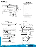
Страница 145: ...141 152 LAUNCHING LAUNCHING RECOMMENDATIONS STEPPING THE MAST 11...

Страница 146: ...142 152 POSITION OF HOISTING CRADLE AND STRAPS Note Measurements are expressed in mm...

Страница 147: ...ater drain valves Retract the speedometer into its housing it may be damaged by the handling belts For the on line engines check the anode at the end of the shaft is in place Check the nut tightening...

Страница 148: ...htness if need be Open the valves and make sure that they are tight with the hull and relevant hose Check the stuffing box for watertightness Refer to chapter 11 Stuffing box Before starting the engin...

Страница 149: ...145 152 WINTER STORAGE LAYING UP PROTECTION AND MAINTENANCE 12...

Страница 150: ...ack into the boat in the upright and side position in order to have minimum contact surfaces During long absence leave the fridge and icebox doors open to avoid mould developing EXTERIOR Thoroughly ri...

Страница 151: ...s grease the terminals and check the battery voltage Fill the fuel tanks to a maximum in order to avoid condensation Please refe to the engine manual for anything relating to the engine Ashore Take th...

Страница 152: ......

Страница 153: ...85505 LES HERBIERS cedex FRANCE Tel 33 02 51 64 20 20 Fax 33 02 51 67 37 65 Internet http www jeanneau com fr The present document is not contractual and since we constantly desire to improve our mode...

Страница 154: ......

Страница 155: ...151 152...

Страница 156: ...152 152...

Отзывы: