background image

22

21-18RT

Instruction & User Manual

2. Close the lock lever.
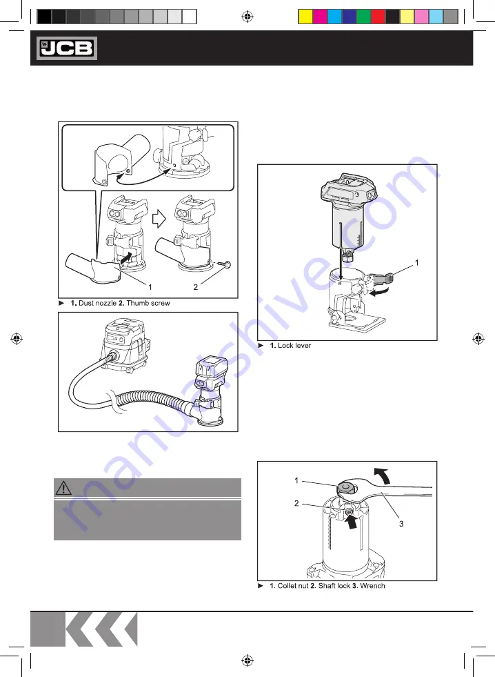
3.  Attach the dust nozzle to the trimmer base, and 

then tighten the thumb screw.


m

To remove the base, follow the installation 
procedure in reverse 

Installing or removing the  
tilt base


m

Optional accessory

1. Open the lock lever of the tilt base, then insert 
the tool into the tilt base aligning the groove on the 
tool with the protrusion on the tilt base.

2.  Close the lock lever. 

To remove the base, follow the installation 
procedure in reverse.

Installing or removing the  
offset base


m

Optional accessory

1. Press the shaft lock, then loosen the collet nut.

When using the tool with the trimmer
base, be sure to install the dust nozzle on the
trimmer base.

WARNING!

2886 21-18RT 2886 21-18RT Brushless Router and Accessories Manual.indd   22

2886 21-18RT 2886 21-18RT Brushless Router and Accessories Manual.indd   22

13/09/2021   10:16

13/09/2021   10:16

Содержание 21-I8RT

Страница 1: ...EN 21 18RT Original Instructions IM 18RT EN Iss 08 2021 2886 21 18RT 2886 21 18RT Brushless Router and Accessories Manual indd 1 2886 21 18RT 2886 21 18RT Brushless Router and Accessories Manual indd...

Страница 2: ...d to a collection system which conforms to the EU Directive 2012 19 EU or the UK Waste Electrical and Electronic Equipment Regulations 2013 It will then be recycled or dismantled in order to reduce th...

Страница 3: ...TECHNICAL DATA 11 BATTERY TECHNICAL DATA 11 CHARGER TECHNICAL DATA 11 NOISE INFORMATION 12 VIBRATION INFORMATION 13 OPERATING INSTRUCTIONS 14 Intended Use 14 Power Switch Operation 14 BATTERY AND CHAR...

Страница 4: ...abuse the cord Never use the cord for carrying pulling or unplugging the power tool Keep the cord away from heat oil sharp edges or moving parts Damaged or entangled cords increase the risk of electr...

Страница 5: ...the risk of starting the power tool accidentally m Store idle power tools out of the reach of children and do not allow persons unfamiliar with the power tool or these instructions to operate the pow...

Страница 6: ...or risk of injury m Do not expose a battery pack or tool to fire or excessive temperature Exposure to fire or temperature above 130 C may cause explosion m Follow all charging instructions and do not...

Страница 7: ...ion of dust Some materials can contain toxic materials Also work with dust chip extraction when connectable Additional Safety Rules For Router Trimmers m Hold the power tool by insulated gripping surf...

Страница 8: ...oward or away from the operator depending on direction of the wheel s movement at the point of pinching Abrasive wheels may also break under these conditions m Kickback is the result of power tool mis...

Страница 9: ...ges Check the rating plate of the charger matches your local supply voltage Note the dual charger can additionally operate on worldwide 100 240V AC 50 60Hz input voltage Do not attempt to use the char...

Страница 10: ...HTS 7 SHAFT LOCK 8 COLLET NUT WITH COLLET CONE INSIDE 9 CLAMP SCREW 10 GRIP 11 CHARGER refer to page 15 for further information 12 BATTERY PACK refer to page 15 for further information 13 BATTERY TEST...

Страница 11: ...8V 2 0Ah 45 mins 30 mins 35 mins 21 30LI Large 10 18V 3 0Ah 65 mins 40 mins 45 mins 21 40LI Large 10 18V 4 0Ah 90 mins 55 mins 60 mins 21 50LI Large 10 18V 5 0Ah 110 mins 65 mins 75 mins Charger Fuse...

Страница 12: ...ool being used in particular on the type of workpiece being processed Try to keep emissions as low as possible for example by limiting your working time In this regard all the operational cycle phases...

Страница 13: ...ke account of all parts of the operating cycle These include times when the power tool is switched off and when it is running idle but not actually doing work This may significantly reduce the total e...

Страница 14: ...rces m To power on the LED tasklights 6 press the LOCK UNLOCK button 1 once m To power off the LED tasklights press the LOCK UNLOCK button again Prior to any assembly adjustment or cleaning operations...

Страница 15: ...evel table below for battery charger status as indicated by LED lights m When the battery pack is fully charged unplug the battery charger from the power supply and remove the battery pack from the ch...

Страница 16: ...hten any loose screws immediately or serious injury could occur Brush inspection m Brush inspection is not required as the power tool motor is brushless for superior longevity and operation Power tool...

Страница 17: ...ng the purpose designed handle m Ensure that the power tool is not at risk of tipping over or exposed to excessive vibration and shocks during transport especially if the tool will be transported by c...

Страница 18: ...art function minimizes start up shock and makes the tool start smoothly Adjusting cutting depth m To adjust the cutting depth open the lock lever then move the tool base up or down by turning the adju...

Страница 19: ...button 4 Push down the tool until the tip of the trimmer bit touches the flat surface and then turn the fixing lever to secure the tool 5 Press down the stopper pole while pressing the feed button unt...

Страница 20: ...dicates 0 9 Turn the head of the stopper pole to obtain the desired depth To increase the depth turn the head counterclockwise To decrease the depth turn the head clockwise 10 Tighten the stopper pole...

Страница 21: ...the tool with the protrusion on the trimmer base ASSEMBLY Always be sure that the tool is switched off and the battery cartridge is removed before carrying out any work on the tool WARNING Do not tigh...

Страница 22: ...g the groove on the tool with the protrusion on the tilt base 2 Close the lock lever To remove the base follow the installation procedure in reverse Installing or removing the offset base m Optional a...

Страница 23: ...s on the base plate and then remove the base plate 5 Open the lock lever of the offset base then insert the tool into the offset base 6 Mount the belt to the pulley by rotating the belt manually 7 Clo...

Страница 24: ...procedure in reverse Installing or removing the plunge base m Optional accessory 1 Open the lock lever of the plunge base then insert the tool into the plunge base all the way aligning the groove on...

Страница 25: ...the installation procedure in reverse Installing or removing the dust nozzle on the plunge base m Insert the dust nozzle into the plunge base as per the diagram Use the two pozi driv screws located i...

Страница 26: ...t and the wing nut 2 Attach the straight guide to the trimmer base with the clamp screw OPERATION Before cutting on the actual workpiece it is recommended to make a sample cut The proper feed speed de...

Страница 27: ...for the straightguide or if the side of the workpiece is not straight the straight guide cannot be used m In this case firmly clamp a straight board to the workpiece and use it as a guide against the...

Страница 28: ...guide Pivot the tool around the nail in the clockwise direction Using the templet guide m Optional accessory m The templet guide allows for repetitive cut with templet patterns by using a templet 1 L...

Страница 29: ...1 mm per turn At the desired distance tighten the clamp screw to secure the trimmer guide 3 Move the tool with the guide roller riding the side of the workpiece Using the tool with the tilt base m Th...

Страница 30: ...and grip m The offset base plate can also be used with a trimmer base and a grip attachment optional accessory for more stability 1 Loosen the screws on the base plate then remove the base plate from...

Страница 31: ...holder into the holes in the plunge base and then tighten the wing bolts 2 Loosen the wing nut on the straight guide and adjust the distance between the bit and the straight guide At the desired dista...

Страница 32: ...kpiece and the cutting position is too wide for the parallel ruler or if the side of the workpiece is not straight the parallel ruler cannot be used In this case firmly clamp a straight board to the w...

Страница 33: ...53 mm 3 8 Wrench 13 Wrench 22 JCB genuine battery and charger OPTIONAL ACCESSORIES Some items in the list may be included in the tool package as standard accessories They may differ from country to c...

Страница 34: ...within the warranty period Should you choose not to register your product within 30 days of purchase your statutory consumer rights will not be affected You will need the original sales receipt as pr...

Страница 35: ...ogether with your sales receipt If a product develops a fault after 30 days a warranty claim must be submitted If you have a warranty claim please take your product original sales receipt and if appli...

Страница 36: ...ONS IN RELATION TO WHICH CONFORMITY IS DECLARED 7 OBJECT OF THE DECLARATION PLACE OF ISSUE NAME ADDITIONAL INFORMATION THE TECHNICAL DOCUMENTATION FOR THE MACHINERY IS AVAILABLE FROM 5ii THE OBJECT OF...

Отзывы: