Jason International, Inc. •
501.771.4477
Page 16 of 20
Customer Service : 800.255.5766
Copyright © 2018 Jason International, Inc.
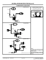
INSTALLATION INSTRUCTIONS (cont.)
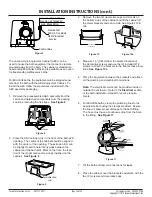
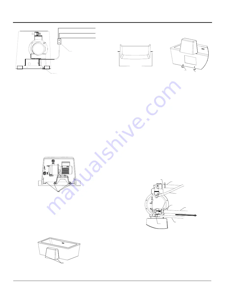
3. Remove the two (2) decorative caps and screws on
the bottom sides of the cabinet and lift the cabinet off
the metal brackets and set it aside. See Figures 12 &
12a
The Jason Acrylic Equipment Cabinet (AEC) can be
used to house the bath equipment that cannot be remote
mounted away from the bath. The cabinet is standard on
freestanding MicroSilk
®
baths and is available as an option
for freestanding AirMasseur
®
baths.
For MicroSilk baths, the equipment will be shipped sepa-
rate from the bath with the AEC Equipment Cabinet. To
install the AEC follow the procedures included with the
AEC assembly packaging
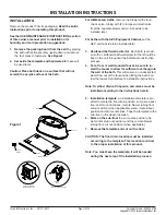
1. Remove the preassembled AEC assembly from the
carton and detach all components from the packing
board be removing the tie straps.
See Figure 8
2. Place the AEC cabinet only in the front of the bath skirt
opening. The center of the cabinet should be aligned
with the center of the opening. The extrusion trim can
be slightly moved to help fill any gaps between the
cabinet and the bath skirt. Mark on the floor, the loca-
tion of the (2) decorative screw caps installed on the
cabinet.
See Figure 9
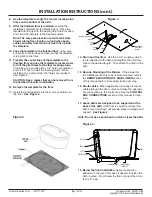
4. Measure 1.5” [3.8cm] from the marked location of
the decorative screws and use the (2) included #12
screws to attach the brackets to the floor at these loca-
tions.
See Figure 10a
5. Place the equipment between the brackets and attach
all the plumbing and electrical connections.
Note:
The electrical service can be provided inside or
outside the enclosure. Refer to the
Electrical
section
of the bath installation manual for service require-
ments.
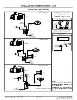
6. For MicroSilk baths, clamp the plumbing lines to the
appropriate barb using the clamps provided. Assure
the line will allow proper drainage to the bath fitting.
The hose must have a continuous drop from the barb
to the fitting.
See Figure 11
7. Fill the bath and test all connections for leaks.
8. Place the cabinet over the brackets and attach with the
two (2) screws and decorative caps.
Droutrn Crz
Fhekdcuhe
120W, 50 rt 60 I
$
HGDN Struhduhe
Vhtxkdh
Htrvoe - Hthho akth
Phvutcn - aikuh akth
Iru - Cncdl akth
#12 Screws
(2)
Metal
Brackets
(2)
Decorative Caps
and Screws (2)
Figure 7
Figure 10
Figure 10a
Tie Straps
Figure 8
Decorative screw
caps
Figure 9
MicroSilk®
Suction Line
MicroSilk®
Drain Line
MicroSilk®
MicroSilk®
MicroSilk®
Suction Barb
MicroSilk®
Drain Barb
MicroSilk®
Discharge Barb
Discharge Line
Priming Barb
& Line
Drainage to Suction & Drain Fitting
Figure 11

