maintenance instructions
Model SHC 140, 165, 165B, 165G, 165GT and 205
page 19 of 20
PRODUCTS CORPORATION
33 ANDERSON ROAD, MIDDLETOWN, CONNECTICUT 06457-4926
UNITED STATES OF AMERICA E--MAIL.
TEL. 860-347-7271
FAX. 860-347-6978
WWW.
jarvisproducts.com
JARVIS
6207016::::.
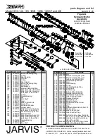
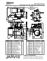
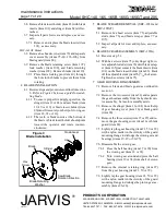
10.7 Replace the o--rings (items 142 and 145) with
new ones from seal kit and apply a liberal coat
of
Jarvis
1315 White Grease
to the o--rings and
drive shaft.
10.8 Install internal retaining ring (item 147).
10.9 Install new seal cartridge (items 142--147) and
internal retaining ring (item 141) into the motor.
10.10 Reassemble the motor to the gear housing, re-
versing procedures outlined in section 7, steps
7.1--7.3.
11 DRIVE SHAFT SEAL REPLACEMENT -- New
Style:
Note: Hydraulic repair kit 3035093 should be available
before disassembling motor.
11.1 Disassemble motor as described in section 12,
steps 12.1--12.8.
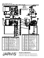
11.2 Remove bearing retaining ring (item 178).
11.3 Slide drive shaft (item 175) with ball bearings
(items 176) from motor front housing (item
169).
11.4 Remove external retaining ring (item 177) and
ball bearings (item 176) from drive shaft (item
175). Inspect and replace if necessary.
11.5 Remove internal retaining ring (item 174).
11.6 Remove seal housing (item 172) with o--ring
(item 173), seal (item 171) and seal retaining
washer (item 170).
11.7 Discard items 152, 171--174 and 178. Replace-
ments are included in repair kit 3035093.
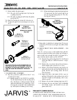
11.8 Reassemble o--ring (item 173) onto seal hous-
ing (item 172).
11.9 Assemble internal retaining ring (item 174), seal
housing (item 172) with o--ring (item 173), seal
(item 171) and seal retaining washer (item 170)
onto drive shaft (item 175).
11.10 Apply a liberal coat of
Jarvis
1315 White
Grease
to all seals, o--rings and drive shaft.
11.11 Gently insert drive shaft and components as-
sembled above into motor front housing (item
169).
11.12 Insert external retaining ring (item 174) into
groove in motor front housing (item 169).
11.13 Reinstall ball bearings (items 176), external re-
taining ring (item 177) and bearing retaining
ring (item 178).
11.14 Reassemble the motor to the gear housing, re-
versing procedures outlined in section 7, steps
7.1--7.3.
12 HYDRAULIC MOTOR DISASSEMBLY:
Note: Cleanliness of the maintenance work area should
be maintained whenever performing any work on the
tool. Due to the exacting nature of the tolerances in a hy-
draulic motor, extra vigilance must be observed. Even
a small amount of foreign matter can cause immediate
failure, or seriously degrade the motor’s performance
and shorten its life. Inspect all parts for dirt or dust prior
to installation and keep them covered with a lint--free
cloth when not working on them.
Note: Never place the motor or any of its components in
a vise. Deformation will occur.
Old and New Style Motors
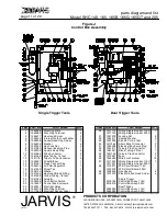
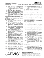
12.1 Separate the gear housing (item 21, 50 or 99) and
motor assembly as outlined in section 7, steps
7.1--7.3.
12.2 Remove the two screws (item 32) and remove
the motor adapter plate (item 29, 52 or 121).
12.3 Remove the four screws (item 67 or 184) and re-
move the hydraulic manifold assembly (items
59--65 or 71--73, 134 and 185--188).
12.4 Remove the four screws (item 179) and separate
the manifold plate (item 163) from the motor.
12.5 Remove the four screws (item 162).
12.6 Gently pull the rear motor housing (item 161 or
164) from the motor.
12.7 Gently remove the motor center plate (item
157).
Be careful not to scratch the bores of the
center plate on the hydraulic gear teeth.
12.8 Remove the two gears (item 156 or 166), the key
(item 154 or 168) and idler shaft (item 155 or
167).
Old Style Motor
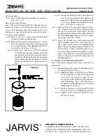
12.9 Remove and disassemble the seal cartridge as
outlined in section 10, step 10.3--10.5.
12.10 Remove the drive shaft and bearing assembly
(items 148--150). Remove the retaining ring
(item 150) from the drive shaft (item 148) and
press the drive shaft from the bearing (item 149).

