maintenance instructions
Model SHC 140, 165, 165B, 165G, 165GT and 205
page 20 of 20
PRODUCTS CORPORATION
33 ANDERSON ROAD, MIDDLETOWN, CONNECTICUT 06457-4926
UNITED STATES OF AMERICA E--MAIL.
TEL. 860-347-7271
FAX. 860-347-6978
WWW.
jarvisproducts.com
JARVIS
6207016::::.
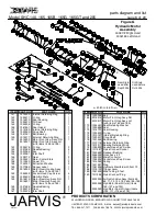
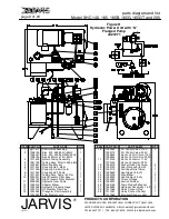
New Style Motor
12.11 Disassemble motor as described in section 11,
steps 11.2 -- 11.7.
Old and New Style Motors
Note: The motor O--rings (item 152) will acquire a per-
manent set in their cross section after they have been in
service. This will reduce their effectiveness upon re--use.
The motor o--rings should always be replaced whenever
the motor is disassembled.
12.12 Remove the two o--rings (item 152) from their
respective housings and discard.
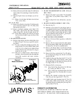
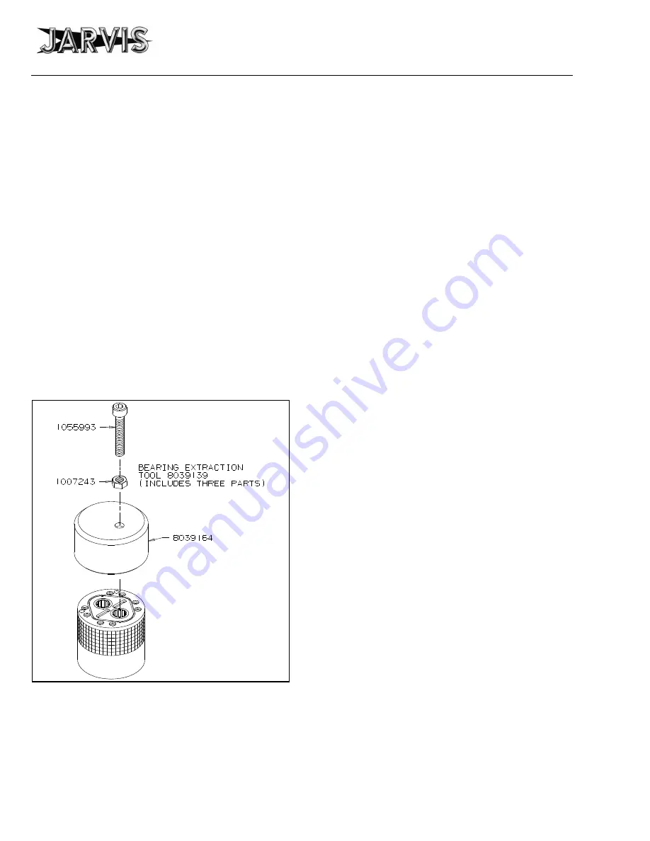
12.13 Remove the needle bearings (item 153 or 165)
from the front and rear motor housings (items
151 or 169 and 161 or 164).
Jarvis
tool 8039139
is available.
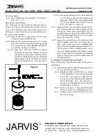
See Figure 6 below.
12.13.1 Insert the 5 mm screw (1055993) and nut
(1007243) through the bearing extraction
tool and into the bearing extraction washer
(item 159). Restrain the screw from rotating
while turning the nut clockwise to remove
the bearing from the bore.
See Figure 6 be-
low.
Figure 6
12.13.2 The needle bearing for drive shaft (item 148
or 175) can be pressed out through the gear
head side of the front motor housing (item
151 or 169).
Jarvis
tool 8039140 is avail-
able.
See Figure 4 on page 18.
12.14 Inspect all parts for wear and replace as neces-
sary. Take special note of the condition of the
bores in the motor center plate (item 157), the
needle bearing journals on drive shaft (item 148
or 175) and idler shaft (item 155 or 167), and the
square key (item 154 or 168).
12.15 Inspect the ground faces of the front and rear
motor housings (items 151 or 169 and 161 or
164), center plate (item 157), manifold plate
(item 163) and hydraulic manifold (item 65 or
187) for nicks or burrs. Small burrs may be re-
moved by lightly polishing the surface on a flat
stone. Larger defects or any defect that intrudes
into an o--ring groove require the replacement of
the damaged part.
13 HYDRAULIC MOTOR ASSEMBLY:
Note: Thoroughly clean all motor components prior to
installation.
13.1 Reverse steps and procedures outlined in section
11.
See special notes below
.
13.1.1
Jarvis
assembly tool 8039140 is available
for the installation of needle bearings (item
153 or 165).
See Figure 4 on page 18.
Al-
ways press on the lip that has the manufac-
turer’s markings.
Note: Pressing the un-
marked (and unhardened) lip will deform
and damage the bearing.
13.1.2 Replace the motor o--rings (item 152) with
new ones before re--assembling the motor.
13.1.3 Tighten screws (item 162 and 179) to 50
lbf--in (5.6 N--m).

