background image

installation and

operation instructions

Model SHC 140, 165, 165B, 165G, 165GT and 205

page 15 of 20

PRODUCTS CORPORATION

33 ANDERSON ROAD, MIDDLETOWN, CONNECTICUT 06457-4926

UNITED STATES OF AMERICA E--MAIL.

[email protected]

TEL. 860-347-7271

FAX. 860-347-6978

WWW.

jarvisproducts.com

JARVIS

6207016::::.

Dual Trigger Tools: Refer to Figure J, page 11.

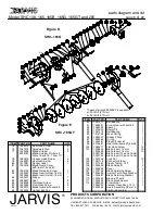
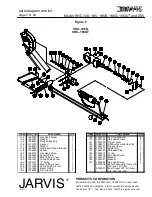
6.3 For the air supply line: use “Y” fitting (item 124,

Figure F, page 7) to connect black plastic tubing
(item 33) from air filter / regulator (item 15) to
blue plastic tubing (item 122, Figure F, page 7)
from the port marked “IN” on hydraulic man-
ifold (item 187, Figure G, page 8), and to blue
plastic tubing (item 125, Figure F, page 7) from
elbow fitting (item 127, Figure F, page 7) closest
to gear head (item 99, Figure D, page 6).

6.4 For the air return line: use tube to tube connec-

tors (item 34) to connect yellow plastic tubing
(item 19) from tube to pipe connectors (item 34)
to yellow plastic tubing (item 126, Figure F,
page 7) from the port marked “OUT” on hydrau-
lic manifold (item 187, Figure G, page 8), and to
yellow plastic tubing, (item 123, Figure F, page
7) from elbow fitting (item 127, Figure F, page
7) furthest from gear head (item 99, Figure D,
page 6.

For Single and Dual Trigger Tools: Refer to Figure H,
page 9 unless noted otherwise.

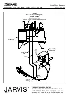
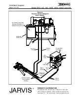
7 Make all necessary hydraulic hose connections.

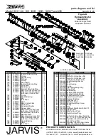
7.1 Connect the quick connect socket (item 29) of

the supply line marked “A” on the hydraulic
power unit to the quick connect plug (item 190,
Figure G, page 8) connected to the hydraulic
manifold port marked “IN.”

7.2 Connect the quick connect plug (item 28) of the

return line marked “B” on the hydraulic power
unit to the quick connect socket (item 180, Fig-
ure G, page 8) connected to the hydraulic man-
ifold port marked “OUT.”

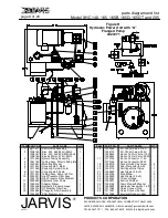
8 Note: There are no adjustments to be made at the hy-

draulic power unit for blade speed or hydraulic pres-
sure. The blade speed is a result of using the full out-
put of the pump and cannot be increased. The pump
is set to a maximum relief pressure of 2000 psi. Dur-
ing operation, the pressure gage (item 13, Figure H,
page 9) will only show the pressure required to make
the cut. The pressure gage should read approximate-
ly 300 psi with the saw running under no load.

OPERATION INSTRUCTIONS

ALWAYS DISCONNECT ALL HYDRAULIC AND AIR
HOSES AND SHUT OFF THE POWER SUPPLY IN

ACCORDANCE WITH OSHA’S LOCKOUT/TAGOUT
PROCEDURES (29 CFR 1910.147) BEFORE PERFORM-
ING ANY REPAIRS OR MAINTENANCE.

1 Turn on the power.
2

Prior to use or daily,

perform the following tests:

For Single Trigger Tools:

2.1 Make sure that the trigger lever (item 188, Fig-

ure G, page 8) is working correctly. Depress the
trigger and the tool should start. Release the
trigger and the tool should stop.

If the tool mal-

functions, remove it from service and report the
problem to your supervisor immediately

.

Always use two hands when starting and
stopping the tool. Continue holding the tool
with two hands until the saw blade comes to
a complete stop.

For Dual Trigger Tools:

2.2 Make sure that the dual anti--tie down control

triggers on the side and rear handles are working
correctly.

Depress

each trigger separately and

the tool should not start.

Depress

one trigger,

then pause one second and depress the other trig-
ger and the tool should not start. Repeat this pro-
cedure reversing the triggers.

Depress

both trig-

gers simultaneously (within one half second of
each other) and the tool should start. With the
tool running,

release

one trigger and the tool

should stop. Continue holding the depressed
trigger and then depress the other trigger. The
tool should not start.

Repeat

this procedure

holding the other trigger.

If the tool malfunc-

tions, remove it from service and report the
problem to your supervisor immediately

.

Always use two hands when starting and
stopping the tool. Continue holding the tool
with two hands until the saw blade comes to
a complete stop.

2.3 Make sure the SHC saw moves freely on the ba-

lancer.

3 Making the cut.

3.1 Position the SHC saw.
3.2 Depress the trigger fully to start the motor and

make the cut.

Always use two hands when starting the tool
and while making the cut.

Содержание SHC 140

Страница 1: ...83 Hydr Power Unit Single Trigger 460V 60Hz 4027271 Hydr Power Unit Single Trigger 440 220V 50Hz 4027274 Hydr Power Unit Dual Trigger 460V 60Hz 4027273 Hydr Power Unit Dual Trigger 440 220V 50Hz 40272...

Страница 2: ...rful This fact should be obvious to your employees but you must emphasize it to them 4 Ensure that employees wear eye protection in accordance with OSHA s eye and face protection re quirements 29 CFR...

Страница 3: ...the cutting path of the tool when it is connected to a power supply 7 Always use both hands when starting and operating the tool to avoid the risk of possible kick back or recoil Continue holding the...

Страница 4: ...Gear Housing LH with items 20 and 22 3016304 Housing Gear Assy RH 3016319 Housing Gear Assy LH items 10 11 and 13 27 ITEM PART NO PART NAME QTY 22 1021373 Needle Bearing 1 23 1026170 Pinion Gear RH 1...

Страница 5: ...d Slotted Screw 2 56 1032494 Rub Plate 1 57 1029028 Spacer 2 58 1033017 Depth Gage Index 1 59 1024149 Trigger Guard 1 60 1055755 Hex Head Screw 2 61 1018131 Trigger Lever 1 62 1019224 Handle 1 63 1055...

Страница 6: ...1 89 1036206 Hanger Bushing 1 ITEM PART NO PART NAME QTY 90 1021471 Ball Bearing 1 91 1026251 Crown Gear with item 93 1 92 1029420 Spacer 1 93 1010522 Dowel Pin 1 94 1021470 Ball Bearing 1 95 1014194...

Страница 7: ...32645 Adapter Plate 1 122 1061670 Blue Tubing 2 feet 1 123 1061457 Yellow Tubing 6 feet 1 124 1051313 Y Fitting 1 125 1071150 Blue Tubing 4 feet 1 126 1071226 Yellow Tubing 8 feet 1 127 1051263 Elbow...

Страница 8: ...r Rear Hsg Assy LH with items 159 and 165 165 1021498 Needle Bearing 4 166 1026279 Gear 2 167 1020405 Idler Shaft 1 ITEM PART NO PART NAME QTY 168 1030099 Key 1 169 3016516 Motor Front Hsg Assy RH 1 3...

Страница 9: ...sure Filter Assy 1 1034105 High Pressure Filter Element 11 3008650 Hydraulic Gear Pump 1 12 1050515 Adapter Elbow 1 13 1025008 Hydraulic Pressure Gage 1 14 1034013 Oil Breather Filler Cap 1 15 1034064...

Страница 10: ...ap Screw 4 13 pg 10 or 11 Control Box Assembly 1 14 1022120 Sub Plate with item 18 1 15 1050462 Hex Nipple 4 inch 1 16 1050090 Hex Nipple 2 inch 1 17 1050126 Pipe Elbow 2 18 1022119 Cartridge Relief V...

Страница 11: ...1051065 Actuator 1 21 1005059 Push Button Switch 1 22 1016347 Control Box Enclosure 1 23 1063011 Electrical Relay 1 24 1063079 Wire Ring Terminal 2 25 1017085 Electrical Danger Label 1 ITEM PART NO PA...

Страница 12: ...OF AMERICA E MAIL sales jarvisproducts com TEL 860 347 7271 FAX 860 347 6978 WWW jarvisproducts com JARVIS 6207016 Figure 1 Hose Connection Diagram Single Trigger Control Box Assembly Factory Installe...

Страница 13: ...roducts com TEL 860 347 7271 FAX 860 347 6978 WWW jarvisproducts com JARVIS 6207016 Figure 2 Hose Connection Diagram Dual Triggers Control Box Assembly Factory Installed on Hydraulic Power Unit Contro...

Страница 14: ...REPAIRS OR MAINTENANCE ALL WIRING MUST BE DONE IN ACCORDANCE WITH NATIONAL STATE AND LOCAL ELECTRICAL CODES RefertoFigure1or2onpage12or13asaguideforcon necting the air and hydraulic hoses 1 Install th...

Страница 15: ...p isset to a maximumrelief pressureof 2000psi Dur ing operation the pressure gage item 13 Figure H page9 willonly showthe pressurerequired tomake thecut Thepressuregageshouldreadapproximate ly 300 psi...

Страница 16: ...toolshouldnotstart Repeatthispro cedurereversingthetriggers Depressbothtrig gers simultaneously within one half second of each other and the tool should start With the tool running release one trigger...

Страница 17: ...Screw Blade Retaining Washer Lip 5 BLADE SCRAPER REMOVAL SHC 165G and SHC 165GT 5 1 Remove hex head screws item 75 adjustable studs item 76 and blade scraper item 77 or 105 5 2 Inspect all parts for w...

Страница 18: ...er smarkings Note Pressing the unmarked and unhardened lip will deform and damage the bearing 8 1 2 Wheninstallinginternalretainingring item 27 make sure that the beveled edge faces away from gear hou...

Страница 19: ...bove into motor front housing item 169 11 12 Insert external retaining ring item 174 into groove in motor front housing item 169 11 13 Reinstall ball bearings items 176 external re taining ring item 1...

Страница 20: ...175 can be pressed out through the gear head side of the front motor housing item 151 or 169 Jarvis tool 8039140 is avail able See Figure 4 on page 18 12 14 Inspect all parts for wear and replace as...

Отзывы: