
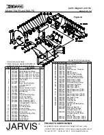

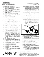

parts diagram and list
Model 700-FS and 900--FS
page 8 of 12
®
JARVIS
6207014::::
PRODUCTS CORPORATION
33 ANDERSON ROAD, MIDDLETOWN, CONNECTICUT 06457--4926
UNITED STATES OF AMERICA E--MAIL.
TEL. 860-347-7271 FAX. 860-347-6978 WWW
.jarvisproducts.com
1
1007355
Hex Lock Nut, 115v
2
1007359
Hex Lock Nut, 220v
2
1004206
Washer, 115v
2
1004234
Washer, 220v
3
1016347
Control Box Enclosure
1
4
1051062
Reducer Pipe Bushing
2
5
1051082
Tube Connector
2
6
1061458
Blue Tubing (16 feet)
1
7
1051119
Tube to Tube Connector
2
8
1055197
Socket Hd Cap Screw, 115v
2
1055198
Socket Hd Cap Screw, 220v
9
1034014
Air Filter
1
10
1061459
Yellow Tubing (16 feet)
1
11
1050300
Square Head Plug
2
12
1051069
Hex Head Bleed Fitting
1
13
1051063
Street Tee
1
14
1004154
Plain Washer
2
15
1051065
Actuator
1
16
1005059
Push Button Switch
1
17
1063083
Ring Wire Terminal
8
18
1063079
Ring Wire Terminal
1
19
1063011
Electrical Relay
1
20
1004244
Internal Tooth Lock Washer
2
21
1055477
Hex Head Screw
2
22
1001014
Electric Cord
4 ft
23
1007278
Locking Nut
2
24
1011240
Strain Relief Connector
2
25
1004211
Sealing Washer
2
26
1032266
Relay Panel
1
27
1063238
Electrical Enclosure Plug
2
28
1051013
Quick Connect Plug
1
1017113
Wiring Diagram Label
1
1017085
Electrical Danger Label
1
3016192
Control Box Assy, 115v
3016219
Control Box Assy, 220v
(details not shown)
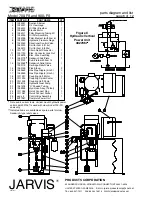
ITEM
PART NO.
PART NAME
QTY
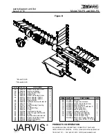
To “IN” or “2”
on manifold
To “OUT” or “1”
on manifold
Cord to Directional
Control Valve
Cord to 115VAC
Power Supply.
Cord Supplied by
Customer
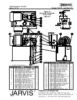
Cord to Directional
Control Valve
Cord to 115VAC
Power Supply.
Cord Supplied by
Customer
Directional
Control Valve
Figure E
Control Box Assembly


