maintenance instructions
Model 700-FS and 900--FS
page 12 of 12
®
JARVIS
6207014::::
PRODUCTS CORPORATION
33 ANDERSON ROAD, MIDDLETOWN, CONNECTICUT 06457--4926
UNITED STATES OF AMERICA E--MAIL.
TEL. 860-347-7271 FAX. 860-347-6978 WWW
.jarvisproducts.com
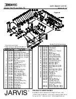
6 GEAR HOUSING DISASSEMBLY:
6.1 Remove blade (item 3).
Refer to steps and pro-
cedures outlined in section 4.
6.2 Remove socket head cap screws and split lock
washers (items 48 and 49).
6.3 Separate motor adapter (item 53) from gear
housing (item 15).
6.4 Remove socket head cap screws (item 52).
6.5 Remove coupling assembly (item 50) and
square key (item 51).
6.6 Remove motor adapter (item 53).
6.7 Remove flat head screws (item 17).
6.8 Remove bearing cover (item 16).
6.9 Remove arbor gear cartridge assembly (items
5-14) from gear housing (item 15).
Lightly tap
gear housing (item 15) with a nylon mallet to
dislodge arbor gear cartridge assembly if nec-
essary.
6.10 Disassemble arbor gear cartridge.
6.10.1 Remove button head screw (item 14) and
lock washer (item 13).
6.10.2 Remove bevel gear assembly (item 6).
6.10.3 Remove bowed retaining ring (item 12).
6.10.4 Remove two (2) bearings (item 10) and
spacer (item 11) from sleeve (item 8).
6.11 Remove pinion gear cartridge assembly (items
20--27 and 19,
if applicable
or items 20, 22--25
and 27--29) from gear housing (item 15).
Note:
Item 19 is not used in current models. Lightly
tap gear housing (item 15) with a nylon mallet
to dislodge pinion gear cartridge assembly if
necessary.
6.12 Disassemble pinion gear cartridge.
6.12.1 Remove external retaining ring (item 19) if
applicable.
Item 19 is not used in current
models.
6.12.2 Remove pinion gear (item 20) using a bear-
ing separator or an arbor press.
6.12.3 Remove woodruff key (item 27).
for old design:
6.12.4 Remove internal retaining ring (item 21).
for new design:
6.12.5 Unthread pinion sleeve (item 29) from
flange (item 28).
6.12.6 Press pinion shaft (item 25), ball bearings
(item 22) and spacers (items 23 and 24) as
an assembly from the pinion sleeve (item 26
or 29) by pushing on the tang end of the pin-
ion shaft.
Be careful not to damage the end
of the pinion shaft.
6.12.7 Remove the four (4) ball bearings (item 22)
and spacers (items 23 and 24) from pinion
shaft (item 25).
6.12.8 Inspect all parts for wear and replace if nec-
essary.
7 GEAR HOUSING ASSEMBLY:
7.1 Reverse steps and procedures outlined in section
6.
See note below.
7.1.1 Install roll pin (item 7) into hole of sleeve
(item 8). The roll pin (item 7) in sleeve must
line up and fit in groove of gear housing
(item 15).
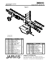
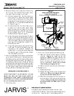
Refer to Figure 3 below as a
guide.
Roll Pin
Groove for
Roll Pin
Gear Housing
Sleeve
Figure 3
8 MOTOR AND TRIGGER DISASSEMBLY:
8.1 Remove long socket head cap screws (item 70)
and trigger guard (item 69).
8.2 Remove shorter socket head cap screws (item
65).
8.3 Separate hydraulic motor (item 55) from hy-
draulic manifold (item 64).
8.4 Remove o-rings (items 56 and 58).
8.5 Inspect the parts for wear and replace if neces-
sary.
9 MOTOR AND TRIGGER ASSEMBLY:
9.1 Reverse steps and procedures outlined in section
8.
See note below.
9.1.1 Port marked “IN” on hydraulic motor (item
55), must align with hydraulic manifold port
furthest from trigger lever (item 67).


