installation and
operation instructions
Model 700-FS and 900--FS
page 10 of 12
®
JARVIS
6207014::::
PRODUCTS CORPORATION
33 ANDERSON ROAD, MIDDLETOWN, CONNECTICUT 06457--4926
UNITED STATES OF AMERICA E--MAIL.
TEL. 860-347-7271 FAX. 860-347-6978 WWW
.jarvisproducts.com
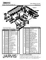
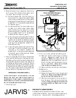
6 Make all necessary hose connections.
Refer to Fig-
ure E on page 8 for referenced items unless other-
wise noted. Refer to Figure 1 as a guide.
6.1 For the air pressure line: Use tube to tube con-
nector (item 7) to connect blue plastic tubing
(item 6) from air filter (item 9) to blue plastic
tubing (item 74, Figure B, page 5) from the port
marked “IN” or “2” on hydraulic manifold (item
64, Figure B, page 5).
6.2 For the air return line: Use tube to tube connec-
tor (item 7) to connect yellow plastic tubing
(item 10) from street tee (item 13) to yellow
plastic tubing (item 75, Figure B, page 5) from
the port marked “OUT” or “1” on hydraulic
manifold (item 64, Figure B, page 5).
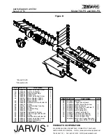
6.3 Connect the quick connect plug (item 78, Figure
B, page 5) from the hydraulic supply line con-
nected to the hydraulic manifold port marked
“IN”, to the quick connect socket (item 24, Fig-
ure D, page 7) of the supply line marked “A” on
hydraulic power unit.
6.4 Connect the quick connect socket (item 77, Fig-
ure B, page 5) from the hydraulic return line
connected to the hydraulic manifold port
marked “OUT”, to the quick connect plug (item
23, Figure D, page 7) of the return line marked
“B” on hydraulic power unit
7 There are no adjustments to be made at the hydraulic
power unit for blade speed or hydraulic pressure.
The blade speed is a result of using the full output of
the pump and cannot be increased. The pump is set
to a maximum relief pressure of 2000 psi. During
operation, the pressure gage (item 26, Figure D, page
7) will only show the pressure required to make the
cut. The pressure gage should read approximately
300 psi with the saw running under no load.
OPERATION INSTRUCTIONS
ALWAYS DISCONNECT ALL HYDRAULIC AND AIR
HOSES AND SHUT OFF THE POWER SUPPLY IN
ACCORDANCE WITH OSHA’S LOCKOUT/TAGOUT
PROCEDURES (29 CFR 1910.147) BEFORE PERFORM-
ING ANY REPAIRS OR MAINTENANCE.
1 Turn on the power.
Figure 1
Hose Connection Diagram
Control Box Assembly
(Factory Installed on Hydraulic Power Unit)
Control Box
Assembly
Hydraulic
Power Unit
Blue
Tubing
Yellow
Tubing
Pressure
Line
Return
Line
Street
Tee
Air
Supply
Inlet
Air
Filter
Yellow
Tubing
Tube to Tube
Connectors
2
Prior to use or daily,
perform the following tests:
2.1 Make sure that the control trigger is working
correctly.
Depress
the trigger and the tool
should start.
Release
the trigger and the tool
should stop.
If the tool malfunctions, remove it
from service and report the problem to your su-
pervisor immediately.
Always use two hands
when starting and stopping the tool.
2.2 Make sure the saw moves freely on the balancer.
3 Making the cut.
3.1 Position the FS saw.
3.2 Depress the trigger fully to start the motor and
make the cut.
Always use two hands when start-
ing the tool and while making the cut.
3.3 When the desired length of cut is reached, re-
lease the trigger. This will stop the blade from
rotating.
Continue holding the tool firmly with
two hands until the saw blade comes to a com-
plete stop.


