The User Manual of JAC200 Series General Frequency Converter
- 98 -
Set range
0.0s
~
3600.0s
The delay from state change to practical output change of output terminal RELAY1, DO1 shall be set.
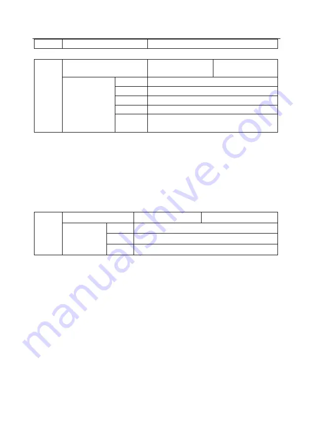
F5-22
Valid state selection for DO
output terminal
Default value
00000
Set range
Ones place
0
Positive logic
1
Negative logic
Tens place
RELAY valid state setting (0
~
1, the same as above)
Thousands
place
DO terminal valid state setting (0
~
1, the same as
above)
The output logic of output terminal RELAY, DO shall be defined.
0
:
Positive logic. Connection of digital value output terminal with corresponding common terminal shall be
valid state and disconnection shall be invalid state.
1
:
Negative logic. Connection of digital value output terminal with corresponding common terminal shall be
invalid state and disconnection shall be valid state.
Group F6 Start-stop control
F6-00
Start mode
Default value
0
Set range
0
Direct start
1
Speed tracking restart
2
Pre-excitation start (asynchronous motor)
0: Direct start
If the start DC braking time is set as 0, the frequency converter shall start from starting frequency.
If the start DC braking time is not 0, the frequency converter shall start from DC braking first and then from
starting frequency. This start mode is applicable to low inertial load, under certain situation, the motor may
rotate when starting.
1: Speed tracking restart
The frequency converter shall judge the speed and direction of motor first, and then start in the motor
frequency tracked. For the rotating motor, it shall start in smooth and no impact mode. This start mode is
applicable to power interruption restart in high low inertial load. To ensure the performance of speed
tracking restart, the motor Group F1 parameters shall be set accurately.
2: Pre-excitation start of asynchronous motor
This start mode is just valid to asynchronous motor and is used to set up the magnetic field before the motor
operates.
See the description for Function code F6-05 and F6-06 for pre-excitation current and pre-excitation time.


