background image

31

Upper feed dog (2)

To adjust:
1.  Follow steps 3 to 5 of “To check” procedure on page 

30 and turn the handwheel toward you to raise the 

needle.

2.  Remove the top cover and face plate.

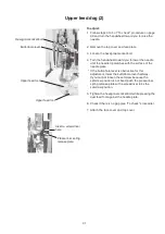
3.  Loosen the hexagonal socket bolt.

4.  Turn the handwheel toward you to lower the needle 

until the needle tip matches with the surface of the 

needle plate.

* If the buttonhole lever is obstructive for this 

adjustment, lower the buttonhole lever half-way. 

If you cannot loosen the setscrew because the 

setscrew position is not fixed, push the presser bar 

spring release plate with a screwdriver to fix the 

setscrew position.

5.  Tighten the hexagonal socket bolt while pressing the 

dual feed foot against the needle plate.

6.  Check if there is no gap (see “To check” procedure).

7.  Attach the face cover and top cover.

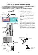
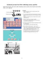
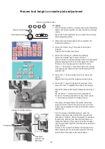
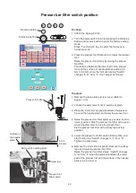
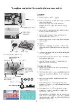
Hexagonal socket bolt

Buttonhole lever

Insert a screwdriver 

here

Presser bar spring 

release plate

Upper feed foot

Upper feed foot

Содержание Continental M7 Professional

Страница 1: ...1 SERVICE MANUAL MODEL Continental M7 Professional First Edition 06 August 2019...

Страница 2: ...ension adjustment 22 Bobbin winder stopper adjustment 23 Needle threader hook position 24 Thread cutter switch adjustment 25 Thread drawing lever height adjustment 26 Automatic upper feed withdrawal r...

Страница 3: ...emove the bobbin winder connector 1 bobbin winder connector 2 and remove the top cover Bobbin winder connector 1 and 2 are located rear side of the touch panel LCD screen To attach 1 Insert the bobbin...

Страница 4: ...se Changing external parts 2 Belt cover To remove 1 Remove the top cover Refer to page 1 Remove the caps and setscrews A 4 pcs and remove belt cover To attach 1 Attach the belt cover and tighten the s...

Страница 5: ...e the thread cutter cover To attach 1 Attach the thread cutter cover with the setscrew B Setscrew B Thread cutter cover Power supply cover To remove 1 Remove the setscrews A 3 pcs and remove the power...

Страница 6: ...cs the printed circuit board F connector the slide volume connector and the rotary encoder connector Remove the front cover To attach 1 Follow the steps of removal procedure in reverse Changing extern...

Страница 7: ...5 Changing external parts 5 To remove 1 Remove the setscrews 3 pcs and remove the rear cover To attach 1 Attach the rear cover with the setscrews 3 pcs Rear cover Setscrew Setscrew Setscrew...

Страница 8: ...Remove the face plate and top cover Refer to page 1 2 Loosen the setscrews 2 pcs and remove the arm thread guide unit To attach 1 Follow the steps of removal procedure in reverse Setscrew Setscrew Arm...

Страница 9: ...3 Remove the setscrews B 4 pcs and disconnect all the connectors from the printed circuit board A Remove the printed circuit board A To attach 1 Follow the steps of removal procedure in reverse Refer...

Страница 10: ...eps of removal procedure in reverse Printed circuit board F Printed circuit board F Slide volume Slide volume To remove 1 Remove the front cover Refer to page 4 2 Remove the snap rings CS 3 2 pcs and...

Страница 11: ...ews A 2 pcs Unhook the front panel 2 from the front panel unit and remove the front panel 2 3 Remove the setscrews B 4 pcs and remove the front panel unit 4 Remove the caps 2 pcs the nuts 2 pcs rotary...

Страница 12: ...panel 2 and front panel unit Refer to pages 4 and 8 2 Remove the setscrews A 4 pcs and LCD unit 3 Remove the setscrews B 3 pcs and LCD supporter plate To attach 1 Follow the steps of removal procedure...

Страница 13: ...2P Presser foot lifting motor Black 8P Upper feed disengagement motor Black 7P Thread tension motor White 7P Bight motor White 7P Printed circuit board B White 5P Blushless DC motor White 14P Printed...

Страница 14: ...is is not the case adjust as follows Loosen the setscrew and turn the eccentric pin The direction of eccentricity should be in the upper part 4 Tighten the setscrew 5 Attach the arm thread guide unit...

Страница 15: ...ch or too little loosen the setscrews of lower shaft bushings both front and rear and adjust the backlash following the adjustment procedure in step 6 Turn the lower shaft bushings front and rear in t...

Страница 16: ...e bar 3 85 mm up from the lowest position by turning the hand wheel toward you 9 Turn the lower shaft gear until the tip of the hook meets the right side of the needle and then tighten the setscrews 2...

Страница 17: ...he setscrew with an allen wrench Move the needle bar and adjust needle bar height to 1 8 mm 8 Tighten the setscrew with the needle setting groove to the front 9 Attach the arm thread guide unit and fa...

Страница 18: ...he factory setting mode Press the Bobbin key When you press Bobbin key in the factory setting mode the maximum stitch width will be set at 9 0 automatically 6 Loosen the setscrew and adjust the cleara...

Страница 19: ...is 0 10 to 0 05 mm 4 Tighten the setscrews A B and C firmly Check the backlash between hook drive gear and lower shaft gear hook timing and needle bar height Adjust if necessary after the adjustment 5...

Страница 20: ...sting mode 4 Press the drop feed key to drop the feed dog Press the presser foot lifter button to lower the presser foot 5 Raise the presser foot lifter lever 6 Loosen the setscrew on the presser bar...

Страница 21: ...the handwheel toward you to raise the feed dog to its highest position 5 Loosen the setscrew A 6 Loosen the nut Adjust the feed dog height by turning the setscrew B 7 Tighten the nut 8 Tighten the set...

Страница 22: ...ront cover and arm thread guide Refer to pages 1 4 and 6 2 Loosen the setscrew A 2 pcs and slide the front cover toward you slightly 3 Remove the setscrew B and setscrew C 4 Remove the thread tension...

Страница 23: ...on release mechanism should work correctly 1 Remove the face plate top cover and front cover Refer to pages 1 and 4 2 Turn the power switch off Turn the thread tension gear until the convex part of te...

Страница 24: ...ch ON while pressing the Start Stop button and the Reverse stitch button Press the BH Sen Tension key to select the BH sensor and tension adjusting mode 3 Thread 50 polyester thread to the machine 4 S...

Страница 25: ...loosen the setscrew and turn the bobbin winder stopper Turn the bobbin winder stopper in the direction of A when the thread amount for bobbin is too large Turn the bobbin winder stopper in the direct...

Страница 26: ...2 If the threader hook is not aligned vertically with the needle eye loosen the setscrew A Adjust the stopper position so that the hook enters into the needle eye 3 Tighten the setscrew A 4 If the thr...

Страница 27: ...g cutter moves to its home position automatically 4 The distance between the left end of moving cutter and the left end of thread cutter plate slit should be 0 7 to 1 5 mm If not adjust as follows To...

Страница 28: ...e hexagonal socket screw When the thread drawing lever is at the highest position adjust the drawing lever so that the distance between the hook race and the drawing lever is 5 5 to 5 7 mm 3 Tighten t...

Страница 29: ...to adjust the clearance 4 Press the Dualfeed key to select the dual feed adjusting mode Press the OFF key at Vertical to move the withdrawal rod to the right Press ON key at Vertical to move the with...

Страница 30: ...be 16 5 mm If not follow the procedure below 5 Loosen the setscrew Adjust the clearance between the upper feed lower shaft 2 and connecting link shaft stool to 16 5 mm Adjust the upper feed dog on nex...

Страница 31: ...ff To initialize the feed dog position be sure to press the needle up down key twice to raise the needle 6 Lower the presser foot lifter and check the clearance The clearance between the dual feed foo...

Страница 32: ...off To initialize the feed dog position be sure to press the needle up down key twice to raise the needle 6 Lower the presser foot lifter 7 Raise the toe of the dual feed foot and leave it as it is 8...

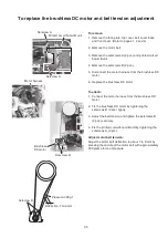
Страница 33: ...r is obstructive for this adjustment lower the buttonhole lever half way If you cannot loosen the setscrew because the setscrew position is not fixed push the presser bar spring release plate with a s...

Страница 34: ...eedle bar crank pin into the take up lever crank as illustrated The setscrew A long must hold the needle bar crank pin cut surface To replace the thread take up lever Needle bar crank pin cut surface...

Страница 35: ...A and the feed cam B are the same as that of the spring pin C The phase of feed lifting pin D is shown below Lower shaft gear Feed cam Thread drawing lever cam Lower shaft gear Feed lifting pin D Feed...

Страница 36: ...lo belt set the alignment mark A on the belt wheel at upper left 10 degrees the alignment mark B on the lower shaft gear at upper right as shown Alignment mark A Belt wheel Alignment mark B Lower shaf...

Страница 37: ...ch 1 Connect the motor harness from the brushless DC motor 2 Fix the brushless DC motor by tightening the setscrews B 2 pcs lightly 3 Adjust the belt tension and tighten the setscrews B 2 pcs securely...

Страница 38: ...ve from the surface of the needle plate If not adjust as follows To adjust 1 Remove the top cover Refer to page 1 2 Turn the handwheel toward you slowly to bring the needle up from its lowest position...

Страница 39: ...buttonhole foot R and lower the buttonhole lever 6 Place a piece of paper under the presser foot to adjust the clearance of buttonhole foot Lower the buttonhole R Adjust the clearance between the stop...

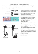
Страница 40: ...5 from the third to the seventh of 8 The length 5 of 8 should be 33 mm to 39 mm Stretch stitch balance dial position 1 Remove the base cap 2 Sew 8 of number 8 3 If the length is longer than 39 mm tur...

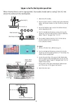
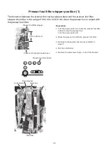
Страница 41: ...presser foot lifter Preparation 1 Turn the power switch on Press the presser foot lifter button to lower the presser foot Turn the power switch off 2 Raise the presser foot with the presser foot lifte...

Страница 42: ...2 Turn the handwheel toward you to lower the needle Raise the presser foot lifter Loosen the hexagonal socket screw of the presser foot lifter stopper from the front side of the machine 3 Adjust the...

Страница 43: ...nsor adjusting mode 3 Press the OFF key to release the gear Turn the gear indicated with black arrow with your hand to raise the presser foot 4 Place the 13 mm spacer between the presser foot and the...

Страница 44: ...g sound is gone 6 Press the again to apply foot pressure then press the set to register the presser bar height Adjust the presser bar height always by pressing key Do not press at the end of this adju...

Страница 45: ...plate 3 Place the 5 mm block spacer between the presser foot and the needle plate and lower the presser foot 4 Raise the presser foot lifter lightly as possible from its lowest position Stop the press...

Страница 46: ...elow tighten the setscrew B securely To adjust and check 1 Prepare the standard needle plate and the straight stitch needle plate 2 Turn the power switch on while pressing the start stop button and re...

Страница 47: ...and ErP switch connector green 2P from the printed circuit board A 3 Remove the setscrews A 4 pcs setscrew B 2 pcs and remove the switching power supply To attach 1 Follow the steps of removal procedu...

Страница 48: ...Check if the feed dog driving arm does not press the drop feed micro switch If not follow the procedure below Setscrew A Drop feed micro switch set plate Feed dog driving arm Drop feed micro switch V...

Страница 49: ...earance between the feed lifting cam and feed lifting cam spring When the feed lifting cam is pushed to the left the feed lifting cam spring should covered with the feed lifting cam completely If the...

Страница 50: ...setting mode Press the Knee lifter key to select the knee lifter adjusting mode 3 Attach the knee lifter Press the MEM1 when the knee lifter is free 4 Push and hold the knee lifter to the right and p...

Страница 51: ...B If not follow the adjustment procedure below Reverse button Wound bobbin Start stop button Needle plate release key Setscrew A Thread cutter unit Setscrew B Light emitting device plate Setscrew A Se...

Отзывы: