11
Wiring diagram
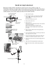
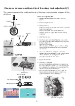
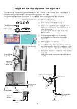
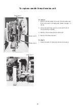
Refer to this wiring diagram for locating the connectors on the printed circuit board A.
(Front side)
(Arm side)
Printed circuit board U2
(Flexible cable)
Printed circuit board L1 (Blue 2P)
Printed circuit board F (Black 18P)
Printed circuit board L2 (White 2P)
Thread cut detection sensor (Black 3P)
Presser foot lifting switch (Black 2P)
ErP switch (Green 2P)
Presser foot lifting motor (Black 8P)
Upper feed disengagement
motor (Black 7P)
Thread tension motor (White 7P)
Bight motor (White 7P)
Printed circuit board B (White 5P)
Blushless DC motor (White 14P)
Printed circuit board L3 (Red 2P)
Printed circuit board L1 (Black 2P)
Rotary encoder (White 6P)
Slide volume (Black 3P)
BH sensor (Black 3P)
Phase sensor (Black 4P)
Printed circuit board U1 (Red 4P)
Printed circuit board B (Black 4P)
Switching power supply
(control) (White 4P)
Switching power supply
(motor) (White 5P)
Printed circuit board U1 (Black 24P)
Printed circuit board U1 (Black 20P)


