Busbar tap-off unit
www.janitza.de
62
11. Mounting
INFORMATION
The following steps show the installation of the
busbar tap-off unit (system BD2 - 125 A variant,
with cover disconnector), regardless of the equip-
ment / installation. Please note, as already de-
scribed under „Installation and equipment op-
tions – schematic diagrams“ on page 60, that the
equipment of your busbar tap-off unit and thus the
information on the mounting of components and
cabling may differ from the following figures!
1x 10 mm
(8 Nm)
DANGER
Life-threatening danger or risk of injury due to
dangerous voltages!
·Before starting work, disconnect your system
and the busbar tap-off unit from the power sup-
ply, secure against reconnection, verify that the
system is voltage-free, ground and short-circuit,
cover or block off adjacent live parts.
·Only qualified electricians and personnel qual-
ified in electrical engineering may perform the
work described below [IEC 61439-1; EN 50110-
1].
·Comply with country-specific safety regulations
and regulations for working near live parts [EN
50110-1].
·Observe additional warnings on the device and
its components.
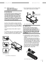
1. Use a hexagon socket wrench or other suitable
tool to open the AKM busbar tap-off unit.
2. The 125 A version of the AKM has a cover
disconnector, which separates the tap-off unit
from the live busbar system when the cover
is opened. This allows shockproof working on
the installed tap-off unit. All other versions of
the busbar tap-off unit do not have a cover
disconnector! In this case, a finger-safe design
provides protection against contact.
Secure the open AKM against being switched
on again; use a padlock, for example, to pre-
vent the AKM from closing.
3. Connect the AKM to the tap-off site of the bus-
bar system. Please note that depending on the
national regulations for electrical installations,
mounting the tap-off units while live might or
might not be permitted. In the second case,
switch off the voltage and protect the bus-
bar circuit against being switched on again in
accordance with local regulations (see warning
symbol).
Starting with the 250 A version of the AKM, it is
fastened to the busbar with a mounting aid that
is included. Please observe the assembly and
installation instructions of the busbar system
manufacturer.
INFORMATION
Check the required space before installing
the AKM. Tap-off units must not be placed at
connection points over terminal blocks! The space
requirements of the AKM must be taken into
account already during the project planning stage!
Please also observe the further assembly and
installation instructions of the busbar system
manufacturer.
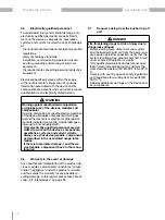
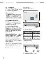
Fig. 1: Open AKM.
Fig. 2: Secure AKM
against being switched
on again.
Fig. 3: Plug the AKM onto the tap-off site of
the busbar.
11.1 Busbar tap-off unit –
System BD2 - 125 A, with cover discon-
nector
Содержание AKM 96RM-E
Страница 13: ...www janitza de 13 Stromschienen Abgangskasten ...
Страница 33: ...www janitza de 33 Stromschienen Abgangskasten ...
Страница 51: ...www janitza de 51 Busbar tap off unit ...
Страница 71: ...www janitza de 71 Busbar tap off unit ...


