www.janitza.de
63
Busbar tap-off unit
L1
L2
L3
N
PE
PEN
L1 L2 L3 N
L1 L2 L3
PEN
TN-C-S
L1 L2 L3 N PE
L1
L2
L3
N
PE
L1 L2 L3 N
L1 L2 L3 N PE
TN-S
PE
N
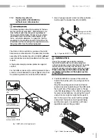
4. Mount the AKM as shown in the adjacent figure
(4). Please note that here too, depending on the
national regulations, the tap-off units may be
live (see warning symbol).
Fig. 4: Fasten the AKM onto the busbar
2x 10 mm
(3 Nm)
INFORMATION
The extremely high diversity in local construction
site conditions cannot be illustrated in this docu-
ment. We therefore recommend that you have the
local conditions checked by qualified installation
personnel.
5. Mount and install your cable to the consumer/
equipment as shown in figure (5). Please note
that this illustration is only for the assembly and
installation of the outgoing cable, the individual
phases, the neutral conductor and the protec-
tive conductor and does not correspond to the
actual, assembled AKM.
Fig. 5: Assembly and installation of the ca-
ble to the consumer/operating equipment.
INFORMATION
A variant of a circuit diagram / wiring
diagram for the AKM can be found in
chapter „Circuit diagram / wiring vari-
1
2
3
4
5
6
3x 13 mm
(12 Nm)
2x 6 mm
(12 Nm)
Fig. 6: Connection of the AKM in TN-S and TN-C-S networks
Содержание AKM 96RM-E
Страница 13: ...www janitza de 13 Stromschienen Abgangskasten ...
Страница 33: ...www janitza de 33 Stromschienen Abgangskasten ...
Страница 51: ...www janitza de 51 Busbar tap off unit ...
Страница 71: ...www janitza de 71 Busbar tap off unit ...


