Jandy WFTR Скачать руководство пользователя страница 14

Page 14 

ENGLISH


Jandy

®

 Pro Series Water Feature Pump   

|

   Installation and Operation Manual

6.2  Service Technician Maintenance

 WARNING

This pump must be serviced by a professional 

service technician, qualified in pool/spa installation. 

The following procedures must be followed exactly. 

Improper installation and/or operation can create 

dangerous electrical hazards, which can cause high 

voltages to run through the electrical system, possibly 

causing property damage, serious injury, or death. 

Improper installation and/or operation will void the 

warranty.

6.2.1  Blocked Impeller

 WARNING

While servicing the pump, switch off the circuit 

breakers at the power source. Severe personal injury 

or death may occur if the pump starts while your hand 

is inside the pump.

1. 

Turn off the pump. Switch off the circuit breaker 

to the pump motor.

2. 

Remove the lid and basket.

3. 

Look inside the pump for debris. Remove any 

debris found inside.

4. 

Replace the basket and lid.

5. 

Switch on the circuit breaker to the pump motor.

6. 

Turn on the pump, and see if the problem is 

solved.

7. 

If the impeller is still blocked with debris and it 

is not possible to remove the debris using Steps 2 

through 4, the pump will need to be disassembled 

in order to access the inlet and outlet of the 

impeller.

6.2.2  Impeller Removal

 WARNING

While servicing the pump, switch off the circuit 

breakers at the power source. Severe personal injury 

or death may occur if the pump starts while your hand 

is inside the pump.

1. 

Turn off the pump. Switch off the circuit breaker 

to the pump motor. If you are not replacing the 

motor, do not disconnect the electrical wiring.

NOTE

  If you are replacing the motor, Zodiac Pool Systems, 

Inc. strongly recommends that a qualified service 

technician or electrician properly disconnect the 

electrical wiring at the pump motor. 

2. 

Turn off any valves to prevent pool water from 

reaching the pump. Drain the water from the 

pump by loosening the unions or removing the  

drain plugs. 

3. 

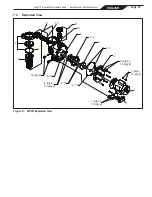
Using a 9/16" wrench, loosen the bolts 

connecting the pump body to the motor 

backplate. See Figure 3.

4. 

Pull the motor and backplate out of the pump 

body. Remove the pump body o-ring. The 

impeller is connected to the motor shaft.

5. 

Using a No. 1 Phillips screwdriver, remove the 

two (2) screws holding the diffuser. (The diffuser 

is the cover over the impeller). Then remove the 

diffuser. See Figure 4. 

6. 

Remove any debris from the inlet and outlet of 

the impeller.

Pump 

Body

Motor Backplate

Bolts (8)

Motor Shaft Cover

Figure 3.  Remove the Pump Housing

Содержание WFTR

Страница 1: ...oduct read and follow all warning notices and instructions that accompany this product Failure to follow warning notices and instructions may result in property damage personal injury or death Imprope...

Страница 2: ......

Страница 3: ...Introduction 7 2 2 Description 7 Section 3 Installation 8 3 1 Plumbing 8 3 2 Electrical Installation 9 3 2 1 Voltage Checks 9 3 3 Pressure Testing 10 Section 4 Operation 11 4 1 Start up 11 Section 5 S...

Страница 4: ...ty damage or injury do not attempt to change the backwash multiport slide or full flow valve position with the pump running WARNING Jandy Pro Series pumps are powered by a high voltage electric motor...

Страница 5: ...visually check system to be sure it is ready for operation NOTICE These parameters apply to Zodiac equipment only For non Zodiac equipment consult equipment manufacturer CAUTION Do not start pump dry...

Страница 6: ...wo 2 main drains run into a single suction line the single suction line may be equipped with a valve that will shut off both main drains from the pump The system shall be constructed such that it shal...

Страница 7: ...trength and corrosion resistance The pump is driven by an electric motor directly attached to the pump impeller As the electric motor turns it causes the impeller to turn which forces water to flow th...

Страница 8: ...nds bolting the pump directly to the foundation 5 The pump foundation must have adequate drainage to prevent the motor from getting wet Protect the pump from the rain and sun 6 Proper ventilation is r...

Страница 9: ...Ball Valves typically have the best flow capabilities 7 Use the fewest fittings possible Every additional fitting has the effect of moving the equipment farther away from the water NOTE If more than 1...

Страница 10: ...o operate simultaneously with the pump such as a chlorinating device or heater to both the pump and motor and will void the warranty 3 2 3 Electrical Wiring WARNING To avoid risk of property damage se...

Страница 11: ...takes to prime will depend on the elevation and length of pipe used on the suction supply pipe See Section 3 1 3 3 Installation Recommendations for proper elevation and pipe size 9 If the pump does no...

Страница 12: ...s have been returned to the proper position for normal operation 9 If a filter is installed in the system open the pressure release valve on the filter and make sure it is clean and ready for operatio...

Страница 13: ...to tighten the union If this does not stop the air leak turn off the pump Loosen both unions and slide the pump out of the way Remove clean and re install both union o rings Reposition the pump next t...

Страница 14: ...Steps 2 through 4 the pump will need to be disassembled in order to access the inlet and outlet of the impeller 6 2 2 Impeller Removal WARNING While servicing the pump switch off the circuit breakers...

Страница 15: ...the impeller from the motor shaft with your hand Since the impeller is a right hand thread turn the impeller counter clockwise to unscrew it 10 Inspect the impeller and diffuser for signs of rubbing a...

Страница 16: ...ou removed the diffuser o ring make sure you install it into the proper groove see Figure 5 If grease is used to retain the o ring it must be silicone based Do not use petroleum based grease It will d...

Страница 17: ...nd following the steps in Section 6 2 3 Impeller Replacement 6 2 5 Motor Replacement CAUTION To ensure continued safety and reliable operation Zodiac Pool Systems Inc requires that you replace the mot...

Страница 18: ...All R0445200 3 Impeller Diffuser w Screw and O ring WFTR 1 0 R0449502 3 Impeller Diffuser w Screw and O ring WFTR 1 5 R0449503 3 Impeller Diffuser w Screw and O ring WFTR 2 5 R0449505 3 Screw w O rin...

Страница 19: ...s Water Feature Pump Installation and Operation Manual Figure 11 WFTR Exploded View 7 2 Exploded View 14 11 8 9 12 10 qty 2 4 15 3 6 11 3 4 14 2 5 2 2 qty 8 16 qty 8 3 15 4 qty 2 15 qty 2 2 13 1 qty 4...

Страница 20: ...eries High Head Pumps WFTR 0 10 20 30 40 50 60 70 80 90 100 110 120 0 10 20 30 40 50 60 70 80 90 100 110 120 130 140 150 160 170 180 190 200 210 220 230 240 250 0 5 10 15 20 25 30 35 40 45 50 WFTR80 1...

Страница 21: ...Carton Weight Overall Length A WFTR80 1 00 230 115 7 1 14 2 2 2 41 2 28 WFTR120 1 50 230 115 8 0 16 2 2 42 6 29 WFTR160 2 50 230 11 5 2 3 48 6 30 NOTE When installing the pump leave a minimum of 2 fe...

Страница 22: ...eries Water Feature Pump Installation and Operation Manual 7 5 Replacement Motor Guide WFTR Replacement Motor Guide Pump Model A O Smith Century Emerson Motor Technologies WFTR80 B853 EB853 WFTR120 B8...

Страница 23: ...Page 23 ENGLISH Jandy Pro Series Water Feature Pump Installation and Operation Manual NOTES...

Страница 24: ...ZodiacPoolSystems com ZODIAC is a registered trademark of Zodiac International S A S U used under license All trademarks referenced herein are the property of their respective owners 2012 Zodiac Pool...

Отзывы: