• Areas with possible obstacles that obstruct
the access to the fan.
The product and its parts must not be submer-
ged in water or other liquids.
The IP rating is only valid if the installation of
the appliance complies with what is indicated
in this manual.
The manufacturer declines all responsibility for
personal injury or damage to animals or objects
caused by inappropriate use of the appliance
according to the warnings for installation, use
and maintenance described in this instruction
manual.
After finishing the installation these instruc-
tions should be given to the owner/user of the
appliance.
The appliance must be able to be disconnected
from the mains electricity supply after installa-
tion.
It can be disconnected by making the plug
accessible or by incorporating a switch in the
fixed wiring that meets electrical installation
standards.
INSTALLATION:
Before starting the installation, check that the propeller is not deformed or
damaged, that it can turn freely, and that no foreign body is lodged inside
the outer casing.”
The appliance shall be installed according to the attached graphic documen-
tation.
It may be installed on the wall or ceiling, with direct exhaust to an individual
exhaust duct (see fig. 1).
If the assembly is done with an individual exhaust tube, place the tube (D) in
the hole prepared for air exhaust.
Whether the assembly is done with an individual exhaust tube or with a
direct outlet, air grilles must be installed that comply with national safety
requirements for preventing access to the fan blades (see fig. 1).
To install, make a circular hole with a diameter corresponding to the model
(80 mm, 100 mm, 120 mm, or 150 mm) in the wall or ceiling where the applian-
ce will be installed, together with the holes for fixing it See Fig 2).
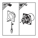
Remove the cover as shown in fig. 3.
Make sure that there is no obstacle blocking the flow of air.
Attach the base of the casing using the plugs and screws supplied by the
manufacturer.
ELECTRICAL CONNECTION:
Make sure that the voltage (V) and frequency (Hz) of the power supply co-
rrespond to the values indicated on the nameplate.”
For fixed installations embedded in the wall or ceiling, the appliance must
have a permanently wired connection that enters through the rear of the
appliance (except in tubular modules that are not embedded).
(Cable rigid or stiff-tipped 2 or 3 wires, with a minimum cross-section of 1
mm2 and maximum of 1.5 mm2).
Remove the circuit cover as shown in fig. 4
To complete the electrical connection, follow the wiring diagram depending
on the model that you wish to connect (see fig. 5).
No earthing connection is required, given that this is a doubly-insulated
appliance (Class II).
The power supply cable must be placed so that no liquid or vapour can enter
the appliance along it. If this were not possible, the cable entry should be
sealed additionally, e.g. with silicone. Otherwise, the indicated IP rating would
not be maintained.
Available versions:
(by model)
• STANDARD. No adjustment required
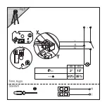
• TIMER. Timer adjustable between 3’ and 15’, or 45”” and 15’, (depending on
the model).
• TIMER-HYGRO. Activated for controlling humidity between 40% and 95%.
Timer adjustable to 3’-15’.
• PULL CORD: activated by pulling the chain.
In the event that this appliance is not used, it is recommended that you dis-
connect it from the mains electricity supply.
Содержание EJ 100 S
Страница 1: ...ES FR EN PT...
Страница 2: ......
Страница 3: ...EJ 100 S EJ 200 S EJ 300 S...
Страница 4: ......
Страница 5: ...40 95 15 3...
Страница 6: ......
Страница 7: ...PULL CORD...

