3
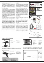
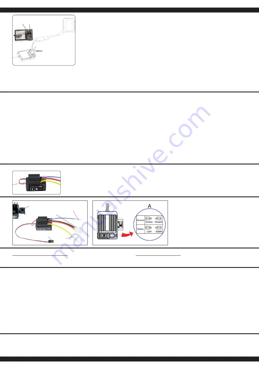
Attacco per la batteria
Battery connector
Cavo di allacciamento
del regolatore
Signal wire
Pulsante ON/OFF
On/Off switch
Attacco per la motore
Motor connector
Attacco per la motore
Motor connector
IT - Allacciare la trasmittente alla ricevente
In un moderno sistema di 2,4 GHz, è indispensabile che la trasmittente e la
ricevente vengano connesse insieme a bordo del modello. La ricevente accetta
quindi solo i segnali della trasmittente. Se per qualsiasi motivo si dovesse ef-
fettuare un nuovo allacciamento“connessione”, eseguire le seguenti operazioni:
A. Sostituire nella trasmettente le batterie scariche con altre cariche o nuove.
Lasciare spenta la trasmettente.
B. Inserire la spina di accoppiamento in dotazione nell’uscita del canale 3.
C. Collegando la batteria con la ricevente, si accende il sistema ricevente.
Secondo la versione di software usata, la ricevente segnala in modo
differente la modalità di binding. (esempio: il Led può lampeggiare,
restare accesa o completamente spenta).
Il processo di binding in se è
uguale per tutte le versioni. Il Led sulla ricevente inizia lampeggiare e
cosisegnala che la ricevente si trova in modalità di binding.
D. Tenere premuto il pulsante di connessione sulla trasmittente, mentre si
accende la stessa.
E. Il trasmittente inizia a lampeggiare e cosi segnala che si trova in modalità di
binding.
F. Rilasciare il pulsante di connessione della trasmettente e rimuovere la
spina di connessione nella ricevente. Spegnere laricevente e la
trasmittente.
G. Adesso spegnete la trasmittente. Il sistema memorizza il collegamento.
H. Installare correttamente tutti gli accessori e controllare con molta
attenzione.
I. Se la funzione non avesse successo, ripetere la procedura di connessione.
L’illustrazione seguente mostra grafi camente il processo di connessione
e specifi ca gli elementi da utilizzare.
GB - Binding the receiber to the transmitter
As with all modern 2.4GHz R/C systems the receiver must be bound to the trans-
mitter to ensure that the receiver will only react to signals from that transmitter.
If you wish to re-bind the receiver with the transmitter please proceed as follows:
A. Ensure that the transmitter is fitted with fresh or fully charged batteries and
leave the transmitter off.
B. Plug the binding plug (included) into the channel 3 socket on the receiver.
C. Switch the receiver system on by connecting the battery or turn in a BEC
operating on a controller to control.
Depending on your software version
of your receiver indicates the different binding mode (instead of flas-
hing lights for example LED or remains out completely).
The binding
process as such is in all versions. The receiver LED will begin to flash
indicating that the receiver is in bonding mode.
D. Press and hold down the binding button on the transmitter whilst switching
it on.
E. The transmitter will begin to flash indicating that the receiver is in bonding
mode.
F. Release the binding button on the transmitter and disconnect the receiver
from the battery or turn off the controller. Release the binding plug from the
receiver.
G. Switch of the transmitter. And remove the binding wire. The system be
bound at the next start .
H. Install all properly and check anything very precisely.
I. If the receiver fails to bond or does not function after bonding repeat the
above procedure until a successful bonding is achieved.
The diagram illustrate the bonding process and show the locations of the relevant
components.
Spina allacciare
Binding Plug
Fail Safe
Setup LED
Programmazione del gruppo integrato di FailSafe
1. Descrizione della Funzione
L’unità FailSafe è concepita principalmente per l‘utilizzo sulle imbarcazioni e sui veicoli. Serve per evitare la
perdita del modello, determinando la chiusura del gas, nell’eventuale assenza di segnale. Se la ricevente
perde il segnale della trasmittente, il servo del gas o regolatore di velocità ritorna automaticamente sulla
posizione programmata inizialmente.
2. Impostazione
a. Accendere la trasmittente
b. Accendere la ricevente. Il segnale LED lampeggia continuamente e indica che la ricevente è pronta.
c. Spostare sul trasmettitore la leva dell‘acceleratore nella posizione di freno, o zona spento nel regolatore di
velocità. Tenere la leva del gas su questa zona.
d. Premere il pulsante Imposta sul ricevitore. Il segnale LED lampeggia per 3 secondi (vedi illustrazione a
sinistra).
e. L‘impostazione è salvata e si può portare la leva dell’acceleratore in posizione neutra.
3. Prova delle impostazioni
a. Accendere la trasmittente.
b. Accendere la ricevente.
c. Spegnere la trasmittente.
d. Ora la ricevente perde il segnale e conduce il servo del canale gas o il regolatore di velocità sulla posizione in
precedenza programmata.
e. Seguire la procedura descritta sopra, il processo FailSafe funziona correttamente.
How to setup the fail safe function
1. The instruction of function
The function of protection of losing control is mainly for r/c boats and cars and keeps them away from damage
through throttle channel. When the receiver is out of control signal, the receiver of throttle will automatically
return to the initial position which set up before starting to avoid the error action :
2. How to set the function
a. Switch on the transmitter power and enter into the working condition
b. Connect the receiver with power and enter into the working condition, the signal light on receiver will blink
all the time.
c. Control the throttle of transmitter and keeps the servo or ESC in the neutral position.
d. Press the setting button, the LED will be flash for 3 seconds (see on pict. left).
e. Release the setting button. The setting is finished.
3. Testing
a. Switch on the transmitter and enter the working condition.
b. Contact the receiver with power and enter the working condition.
c. Turn off the power of transmitter.
d. The throttle of servo will be set automatically.
e. Finish these steps above means the setting is ok.
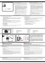
IT - Regolatore (installato) | GB - Controller (installed)
IT - Dati technici
Voltaggio
7,2 - 7,4 V
Batterie
2 Lipo | 6 NiCd/NiMh Celle
Resistenza interna
Fwd: 0.002 Ohm, Bwd: 0.004 Ohm
Tensione BEC
BEC 2A/5V (Linear mode BEC)
Uso
RC-Car 1:10
Protezione
Sottotensione
Carico continuo
40 A
Dimensioni
~ 45 x 32 x 26 mm
GB - Technical Data:
Operating Voltage
7,2 - 7,4 V
Battery Pack
2 Lipo | 6 NiCd/NiMh Cells
Internal Resistance
Fwd: 0.002 Ohm, Bwd: 0.004 Ohm
BEC Voltage
BEC 2A/5V (Linear mode BEC)
Intended use
RC-Car 1:10
Protection Circuit
Under voltage cut off
Continuous load
40 A
Size
~ 45 x 32 x 26 mm
Se si utilizza una batteria Lipo, é necessario attivare il Lipomodo attraverso
il Jumper (connessione ponticello). Prima di raggiungere la sua tensione
minima, il suo regolatore si spegnera. Solo cosi la batteria Lipo viene pro-
tetta del sottocarico o eventuali danni! Sulla soglia di 6 V tensione totale, il
regolatore si spegne per evitare che la batteria si sottocarica. Se si utilizza
una batteria NiMh deve mettere il jumper in posizione NiMh. Il regolatore
non si spegne a 6 V di tensione totale ma permette una scarica di ca. 4 V
tensione totale.
This regulator has two battery modes which will be set with jumpers. If
you are using a Lipo battery this jumper has to be set to Lipo. This func-
tion protects the lipo battery against deep discharge and possible damage
due to deep discharge! At a threshold voltage of 6 V total the esc switches
autom. off to safe the battery from under voltage. If you are using a NiMH
battery this jumper has to be set to NiMh. The controller allows a voltage
less than 6 V down to 4 V.
ATTENZIONE
Il tuo modello è protetto d’antispruzzo. Non impermeabile!
Non guidare in pozzanghere dove l‘acqua è più alta della box ricevente. Non immergere il regolatore sott‘acqua. Se
la ricevente oppure il regolatore all’interno si bagna, separare immediatamente la rete elettrica e lasciarlo asciugare
a sufficienza. Danni causati da uso improprio o mancanza di manutenzione del modello non sono coperti dalla
garanzia.
WARNING
Your controller is Splash-proof. Not waterproof.
Avoid puddles that are higher than the controller is installed in the vehicle. Do not get the model under water. After
each ride in the wet, the complete controller must be thoroughly dried and lubricate the mechanical components.
Damage caused by improper use overload or lack of maintenance is not covered under warranty.
Attivazione del regolatore
Nell’attivazione procedete come segue:
• Accendere la trasmittente e assicurarsi che la regolazione della corsa del canale gas è impostata esattamente
su + / - 100%.
• Collegare la batteria, controllare che la batteria è collegata con la polarità corretta e che il regolatore non sia
ancora acceso.
• Accendere la ricevente.
• Quando la batteria è collegata, il regolatore è pronto. Siate molto cauti, ci sono rischi significativi di lesioni,
tramite la partenza di motori ad improvviso.
• Collegare la batteria immediatamente prima dell´inizio d´uso con il regolatore e rimuovere subito dopo l´uso.
Prima dell’utilizzo del modello, fare un test del raggio d´azione.
• Cosi controllate tutti i campi d´uso (tutto gas, a mezzo gas e minimo), se non vi è alcuna interferenza. Prestare
inoltre attenzione ai servi. Un vibrazione dei servi o deviazioni non controllate, segnala inoltre dei guasti.
• Se si desidera attivare il freno, mentre il veicolo è in movimento in avanti e lo stick del gas è in posizione
avanzata, è necessario spostare lo stick velocemente e invertire la posizione.
• Per mettere la retro-marcia, spostare lo stick in posizione neutra, attendere qualche istante e poi portare lo stick
di là di questo punto, nella posizione inversa desiderata.
GB - Using your controller
To operate the ESC, proceed as follows:
• Switch on your transmitter and ensure that the throw for the throttle channel is set to +/- 100%.
• Ensure that the receiver switch is in the OFF position and connect a battery pack ensuring the correct polarity
(+ and -).
• Switch the receiver system ON.
• Once a battery is connected the system is ‘live‘ and extreme caution must be exercised to prevent injury due to
the motor suddenly starting to turn.
• Do not connect the battery pack until directly before operating the model and disconnect the pack immediate
after use.
• Conduct a range test before running the model for the first time. This test should be carried out at full, half and
low throttle and if the servos jitter or make uncontrolled movements do not operate the model until the reason
for the interference has been established and corrected.
• When the vehicle is being driven forwards, pulling the throttle back past the neutral position will cause the
vehicle to brake. To make the vehicle then reverse, the throttle stick must first be moved back to the neutral
position for a short period and then the model will reverse.
• If you want to disable the backward function just set the jumper to disable. If the jumper is set to enable the
backward function is enabled.
Configurazione del regolatore
Il regolatore di velocità calibra automaticamente il segnale del trasmettitore. Per ottenere questo, il controllo trim del
canale gas del trasmettitore deve essere in posizione neutro. Accendere prima la trasmettente e dopo il regolatore.
Quando il regolatore di velocità, ha riconosciuto la taratura, lo segnala con una breve melodia ed è pronto per l´uso.
Se il regolatore non rileva un chiaro segnale o non si trova in una posizione neutra, il regolatore non s’inizializza.
GB - Configuring your controller
The speed controller automatically calibrates itself to the transmitter signal. For this, the trim button of the gas
channel at the transmitter must be set to neutral. Turn on the transmitter and then the speed controller. The speed
controller signals the calibration with a short melody and is ready for use. In case the speed controller has no clear
signal or the trim control is not set to neutral, the speed controller will not initialize.


