background image

— 24 —

GO-5100MP-PGE

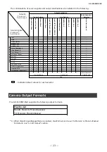
Camera Image Output Modes

The GO-5100MP-PGE has two output modes(Raw Image mode, Polarize Angle And Degree mode).

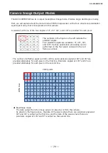
First, we will explain about the monochrome CMOS image sensor with a four-directional polarization 

square pixel array that is incorporated in this camera.

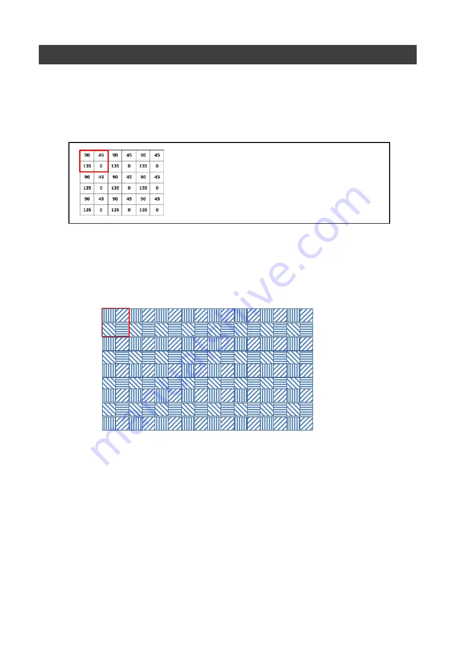
A polarizer with one of the four angles of 0º, 45º, 90º, and 135º is provided for each pixel.

The numbers in the figure on the left indicate the 

polarizer angles.

Four polarizer angles are available: 0º, 45º, 90º, 

and 135º. Various polarization processing can be 

performed on the four pixels enclosed in the red 

frame as a block.

The number of effective pixels is 2464 x 2056, and polarizers angled at 90º and 45º are 

provided alternately for each pixel on the first line. Polarizers angled at 135º and 0º are 

provided alternately for each pixel on the second line.

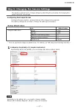
2464 pixels

2056 

lin

es

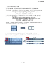
RawImage mode

The data output from the image sensor is output as is from the camera.

As shown in the figure above, the data of the pixels where there are polarizers angled at

90º and 45º is output as the first line, and the data of the pixels where there are

polarizers angled at 135º and 0º is output as the second line.

Содержание GO-5100MP-PGE

Страница 1: ... Thank you for purchasing this product Be sure to read this manual before use This manual includes important safety precautions and instructions on how to operate the unit Be sure to read this manual to ensure proper operation The contents of this manual are subject to change without notice for the purpose of improvement 2019 JAI ...

Страница 2: ...al Input Output Settings 22 Camera Output Formats 23 Camera Image Output Modes 24 Binning Function 26 12 bit Output 29 ROI Regional Scanning Function 29 Image Acquisition Controls 30 Exposure Mode 32 Trigger Control 33 2 GO 5100MP PGE Gain Control 38 Line Status 38 Blemish Compensation 39 Shading Correction 40 Sequencer Function 42 Delayed Readout 44 CounterAndTimerControl Function 44 Chunk Data F...

Страница 3: ...ed and found to comply with the limits for a Class B digital device pursuant to Part 15 of the FCC Rules These limits are designed to provide reasonable protection against harmful interference in a residential installation This equipment generates uses and can radiate radio frequency energy and if not installed and used in accordance with the instructions may cause harmful interference to radio co...

Страница 4: ...on on Measures for the Administration of the control of Pollution by Electronic Information Products known as China RoHS The table shows contained Hazardous Substances in this camera mark shows that the environment friendly use period of contained Hazardous Substances is 15 years ...

Страница 5: ...atterns vertical aliasing zigzag distortion may appear on the monitor Blooming When strong light enters the camera some pixels on the CMOS image sensor may receive much more light than they are designed to hold causing the accumulated signal charge to overflow into surrounding pixels This blooming phenomenon can be seen in the image but does not affect the operation of the camera Fixed pattern noi...

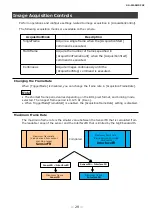
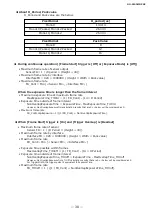
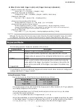
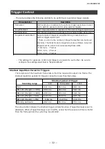
Страница 6: ...mount flange back 17 526 mm Pixel size 3 45 um 3 45 um Effective pixels 2464 H 2056 V Up to 22 7 fps at full resolution Internal test signal for settings configuration eBUS SDK for JAI that supports Windows 7 8 10 GO 5100MP PGE Image sensor with four directional polarization Polarizers are provided for individual pixels to capture polarization The numbers in the figure on the left indicate the pol...

Страница 7: ...confirm the precautions for attaching a lens and the supported lens types RJ 45 connector Connect a Gigabit Ethernet compatible LAN cable Category 5e or higher Category 6 recommended here 7 GO 5100MP PGE Pin No Input Output Description 1 In Out MX1 DA 2 In Out MX1 DA 3 In Out MX2 DB 4 In Out MX3 DC 5 In Out MX3 DC 6 In Out MX2 DB 7 In Out MX4 DD 8 In Out MX4 DD ...

Страница 8: ...gger ACT LED Indicates the GigE network status LINK LED Indicates whether the GigE network connection is established or not DC IN TRIG connector 6 pin round Connect the cable for a power supply optional or for DC IN trigger IN here HR10A 7R 6PB 73 Hirose Electric or equivalent Pin No Input Output Signal Description 1 DC In DC 12 V 24 V 2 In Opto In 1 GPIO 5 3 Out Opto Out 1 GPIO 1 4 Out Opto Out 2...

Страница 9: ...circuit diagram reference example Standard circuit diagram example 9 GO 5100MP PGE User Side JAI Camera User side CAMERA side Recommended external input circuit diagram reference example User Side JAI Camera User side CAMERA side ...

Страница 10: ... holes when attaching an MP 43 tripod adapter plate optional or mounting the camera directly to a wall or other structural system The smaller holes x4 are M2 with a depth of 3mm 10 GO 5100MP PGE Characteristics of the recommended circuits for Opto OUT ...

Страница 11: ...es for adjusting the gain and black level as examples and adjust the image quality Step 7 Saving the Settings Save the current setting configurations in user memory Step 1 Installing the Software first time only 11 When using the camera for the first time install the software for configuring and controlling the camera eBUS SDK for JAI on the computer When you install eBUS SDK for JAI eBUS SDK for ...

Страница 12: ...11 mm diagonal Some lens manufacturers offer lenses with an 11 mm format If not a 2 3 inch lens is recommended 12 The maximum performance of the camera may not be realized depending on the lens Attaching a lens with a mount protrusion of 9 mm or longer may damage the lens or camera Caution Lens Camera body or to external trigger DC IN trigger IN connection cable AC adapter not supplied power suppl...

Страница 13: ...compatible network card Refer to the specifications of the cable for details on its bend radius Secure the locking screws on the connector manually and do not use a driver Do not secure the screws too tightly Doing so may wear down the screw threads on the camera Tightening torque 0 147 Nm or less Secure manually Do not secure too tightly Network card Install this in the computer that will be used...

Страница 14: ...nd PC Verify whether the camera is properly recognized via eBUS Player for JAI Connecting the Camera to eBUS Player for JAI 1 Startup eBUS Player for JAI eBUS Player for JAI startup screen appears GO 5100MP PGE DC IN trigger IN connection cable AC adapter power supply if necessary Connect the AC adapter and the round connector of the connection cable to the DC IN trigger IN connector on the camera...

Страница 15: ... 15 Push Select Connect button The connected camera is listed Please select one camera 2 Select the camera you want to configure GO 5100MP PGE ...

Страница 16: ...vice control button The screen shown below will be displayed In this window you can adjust various settings of the camera This completes the procedure for verifying whether the camera is properly recognized and whether control and settings configuration are possible GO 5100MP PGE ...

Страница 17: ... as necessary Factory default values Item Default value ImageFormatControl Width 2464 Height 2056 OffsetX horizontal position 0 OffsetY vertical position 0 PixelFormat Mono8 You can specify the image acquisition area For details see ROI Regional Scanning Function 1 Configuring the Width of ImageFormatControl By selecting the item of Width you can change the value as shown below Note Depending on t...

Страница 18: ...ting the Image Quality Display the camera image and adjust the image quality Displaying the Image Display the image captured by the camera When you push Play button the camera image appears in right area GO 5100MP PGE ...

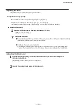
Страница 19: ...fault setting 2 Configure the gain Expand AnalogControl and select the gain you want to configure in GainSelector AnalogAll master gain can be configured Configure the gain value in Gain AnalogAll master gain can be set to a value from x1 to x16 the analog gain value The resolution is set in x0 1 steps Values are configured by multipliers GO 5100MP PGE Adjusting the Black Level 1 Expand AnalogCont...

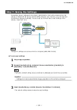
Страница 20: ...er eBUS SDK for JAI To save user settings 1 Stop image acquisition 2 Expand UserSetControl and select the save destination UserSet1 to UserSet3 in UserSetSelector Note The factory default setting values are stored in Default and cannot be overwritten Settings can only be saved when image acquisition on the camera is stopped Caution eBUS SDK for JAI Player 一時メモリ UserSet1 UserSet2 UserSet3 DefaultSe...

Страница 21: ...er settings can only be loaded when image capture on the camera is stopped 2 Select the settings to load UserSet1 to UserSet3 in UserSetSelector 3 Select UserSetLoad and click Execute UserSetLoad Command The selected user settings are loaded GO 5100MP PGE ...

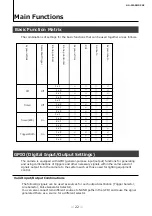
Страница 22: ...ent control Valid Input Output Combinations The following signals can be used as sources for each output destination Trigger Selector Line Selector Pulse Generator Selector You can also connect two different sources to NAND paths in the GPIO and reuse the signal generated there as a source for a different selector GO 5100MP PGE TriggerSequencerMode CommandSequencerMode ROI GainAuto Sequencer Expos...

Страница 23: ...tput 1 Software Trigger Action 1 Action 2 FVAL LVAL Exposure Active Frame Trigger Wait Frame Active Acquisition Trigger Wait Pulse Generator Clear Source Signals to use as output Output destination NAND 1 In 1 NAND 1 In 2 Pulse Generator 0 Time Stamp Reset NAND 0 In 1 NAND 0 In 2 Acquisition Start Acquisition End Frame Start Transfer Start Trigger Source Line Source Use Line Selector Line2 OPT Out...

Страница 24: ... and 135º Various polarization processing can be performed on the four pixels enclosed in the red frame as a block The number of effective pixels is 2464 x 2056 and polarizers angled at 90º and 45º are provided alternately for each pixel on the first line Polarizers angled at 135º and 0º are provided alternately for each pixel on the second line 2464 pixels 2056 lines RawImage mode The data output...

Страница 25: ... represent proportions of polarized light from 0 to 100 8 bit output 00000000 to 11111111 10 bit output 0000000000 to 1111111111 As shown in the figure below two polarimetric parameters of Polarize Angle and Polarize Degree are calculated for a given pixel block and output from it AoLP DoLP As shown below AoLP and DoLP data are alternately output as a single line of data representing the first two...

Страница 26: ...d binning function cannot be used at the same time 3 PixelFormat is one of Mono8 Mono10 and Mono10p 4 VideoProcessBypassMode is Off When horizontal binning only 2x1 The signal values of the pixels having polarizers at the same angle are combined The signal values of the two pixels indicated by the red frames in the following figure are combined The image data output from this camera becomes RawIma...

Страница 27: ...en horizontal and vertical binning 2x2 The signal values of the pixels having polarizers at the same angle are combined The signal values of the four pixels indicated by the red frames in the following figure are combined The image data output from this camera becomes RawImage with 1232 pixels horizontally x 1028 lines vertically 1232 pixels 1028 lines ...

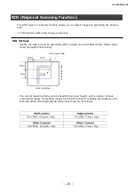
Страница 28: ...s Specify the area to scan by specifying width height and horizontal vertical offset values under ImageFormatControl 2464 Width Max 2056 Height Max Scanning range You can increase the frame rate by specifying a lower height as the number of lines scanned decreases The setting ranges for the ROI function s readable area based on the Binning setting BinningHorizontal BinningVertical are as follows ...

Страница 29: ... maximum frame rate is the smaller value between the SensorFR that is calculated from the readable range of the sensor and the InterfaceFR that is limited by the GigE bandwidth Maximum frame rate Value derived from sensor scanning range SensorFR Maximum frame rate Value derived from GigE bandwidth InterfaceFR Compared SensorFR InterfaceFR SensorFR InterfaceFR Maximum frame SensorFR Maximum frame I...

Страница 30: ...al NonOverlapExposureTime ExposureTime MaxExposureTime_TrOlrd However NonOverlapExposureTime calculation results that are 0 or below will be considered as 0 Maximum frame rate FR_ContLongExposure 1 1 FR_Cont NonOverlapExposureTime Maximum frame rate of sensor Sensor FR 1 H Period Height 40 Maximum frame rate by interface Interface FR 920 1000000 Height Width Pack value Maximum frame rate FR_Cont M...

Страница 31: ...o configure the settings described in Trigger Control ExposureMode Description Off Exposure control is not performed free running operation Timed Mode in which control is performed using exposure time Acquire images using an exposure time configured beforehand on an external trigger TriggerWidth Mode in which control of the exposure time is performed using the pulse width of the trigger input sign...

Страница 32: ...rnal trigger signal input Select this to perform exposure control using external triggers AcquisitionStart Start image acquisition in response to the external trigger signal input AcquisitionEnd Stop image acquisition in response to the external trigger signal input AcquisitionTransferStart Output acquired images at a specified timing in response to an external trigger signal input There is a limi...

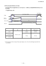
Страница 33: ...rOverlap Off GO 5100MP PGE Next trigger disabled Next trigger Input enabled t2 Exposure time t3 Trigger Sensor Exposure ExposureActive Readout If the exposure time is longer than input trigger cycle t3 the next trigger input will not be accepted t1 t1 t2 t3 minimum 8 bit 40 μs 28 ms 10 bit packed 10 bit 10 μs minimum 79 μs 55 ms ...

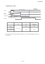
Страница 34: ...ger Input enabled t2 Exposure time t3 Trigger Sensor Exposure ExposureActive Readout t1 t1 t2 t3 minimum 8 bit 40 μs 173 μs 10 bit packed 10 bit 10 μs minimum 79 μs 328 μs If the exposure time is longer than input trigger cycle t3 the next trigger input will not be accepted ...

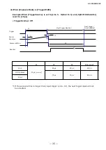
Страница 35: ...iggerOverlap Off GO 5100MP PGE Next trigger disabled Next trigger Input enabled t2 t4 Trigger Sensor Exposure ExposureActive Readout t1 t3 t1 t2 t3 t4 minimum 8 bit 40 μs 40 μs 28 ms 10 bit packed 10 bit 10 μs minimum 79 μs 79 μs 55 ms If the exposure time is longer than input trigger cycle t4 the next trigger input will not be accepted ...

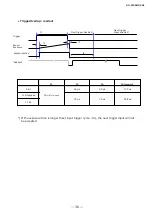
Страница 36: ...r Input enabled t2 t4 Trigger Sensor Exposure ExposureActive Readout t1 t3 t1 t2 t3 t4 minimum 8 bit 40 μs 40 μs 173 μs 10 bit packed 10 bit 10 μs minimum 79 μs 79 μs 328 μs If the exposure time is longer than input trigger cycle t4 the next trigger input will not be accepted ...

Страница 37: ...24dB x 16 x 1 0 GO 5100MP PGE LineStatus The line status function allows you to verify the status of external input output signals You can verify the status of the following signals Opt Out 1 Opt Out 2 Opt In 1 Time Stamp Reset NAND 0 In 1 NAND 0 In 2 NAND 1 In 1 NAND 1 In 2 ...

Страница 38: ...camera s internal memory To check the number of interpolated pixels after automatic detection You can check the number of pixels interpolated via automatic detection by loading the BlemishNum data Manual configuration 1 Select the index in BlemishCompensationIndex You can select from 0 to 255 However configure the indexes in order starting with the smallest index If you skip indexes while configur...

Страница 39: ...s for the camera is 2464 H 2056 V The ineffective peripheral areas will be deleted internally on the camera automatically GO 5100MP PGE The following shading correction mode is available on the camera FlatShading Correction is performed using the area of the screen with the highest brightness level as the reference and adjusting the brightness levels of the other areas to match this level Pre corr...

Страница 40: ...ation Note After shading correction is executed the shading correction value is automatically saved to the user area selected in ShadingMode GO 5100MP PGE Item Setting value Description ShadingCorrectionMode FlatShading Select the shading correction mode ShadingMode User1 User2 User3 Off Select the user area to which to save the shading correction value ...

Страница 41: ...s the camera to the time of the master clock Transport to be used Multicast UDP datagram 224 0 1 129 However Delay_Resp is a unicast UDP datagram Destination port number 319 Sync Delay_Req Pdelay_Req Pdelay_Resp 320 Announce Follow_Up Delay_Resp Pdelay_Resp Management Signaling Items for synchronization Time synchronization is performed Frequency tuning is not performed PTP time data 80 bit elapse...

Страница 42: ... frame trigger frame start exposure start and exposure transfer end and by comparing these values you can determine the internal camera state at which missed triggers will occur Counter occurrence diagram FrameStartTrigger Counter0 ExposureStart Counter1 Event occurrence Count up Counter0 Request Read out value Counter reset Count up Counter1 Request Read count value Counter reset Count 0 reset Co...

Страница 43: ...ctivation Rising Edge or Falling Edge Specify the timing at which to count Item Counter 0 to 2 The three counter event signals are always counted up internally on the camera Video Process Bypass Mode The video process bypass mode is a function that bypasses internal video processing on the camera When bypass is enabled the sensor output and camera output data can be set to the same bit width Opera...

Страница 44: ... when an event occurs at each event AcquisitionTrigger FrameStart FrameEnd Jai FVAL Start Jai FVAL End Exposure Start Exposure End OptOut1RisingEdge Line2RisingEdge OptOut2RisingEdge Line3RisingEdge OptIn1RisingEdge Line5RisingEdge OptOut1FallingEdge Line2FallingEdge OptOut2FallingEdge Line3FallingEdge OptIn1FallingEdge Line5FallingEdge Detect an event Keep the event type and timestamp value when ...

Страница 45: ...ngs of the camera 1 Specify ActionDeviceKey 2 Then specify two actions that can be configured on the camera Action1 Select 1 in ActionSelector Specify ActionGroupMask ActionSelector Specify ActionGroupKey ActionSelector Action2 Select 2 in ActionSelector Specify ActionGroupMask ActionSelector Specify ActionGroupKey ActionSelector 3 Set triggers AcquisitionStart AcquisitionEnd FrameStart Acquisitio...

Страница 46: ...orizontal 1 0 to 2448 step 16 BinningHorizontal 2 0 Fixed 0 Set the horizontal offset BinningVertical 1 0 to 2052 step 2 BinningVertical 1 0 Fixed 0 Set the vertical offset Sum Average Sum Set the addition process to be used during horizontal binning 1 2 1 Set the number of pixels in the horizontal direction for which to perform binning Sum Average Sum Display the addition process to be used durin...

Страница 47: ...r Overlap Off ReadOut Off Select the trigger overlap operation Trigger Delay μs 0 to 500000 0 Set the time to delay the trigger Off Timed Trigger Width Timed Select the exposure mode 8 bit 1 to 7999812 10 12 bit 1 to 7999631 43864 Set the exposure time The specifiable range varies depending on the Start Trigger Mode and Pixel Format setting Off Continuous Off Set whether to enable auto exposure Se...

Страница 48: ...or the item selected in LineSelector Line Inverter True False False Enable disable polarity inversion for the selected input signal or output signal Line Status True False ー Display the status of the input signal or output signal True High False Low Line Mode Input Output ー Display the input output status whether it is input or output Line Format ー Opto Coupled Display the signal format ー 0x0 Disp...

Страница 49: ... the start point of the Low interval as a clock count When the counter reaches this value the output will be 0 Pulse Generator End Point ms 0 00222222 to 2330 17 33 3333 Set the start point of the Low interval in milliseconds When the counter reaches this value the output will be 0 The setting range varies depending on the ClockPreScaler value Pulse Generator Pulse Width ms 1 79769e 308 to 1 79769...

Страница 50: ...set the IP configuration to persistent IP GevCurrentIPAddress ー ー Display the IP address GevCurrentSubnetMask ー ー Display the subnet GevCurrentDefaultGateway ー ー Display the default gateway ー ー Display the first URL ー ー Display the second URL ー 1 Display the number of interfaces ー ー Set the Persistent IP address ー ー Set the Persistent subnete mask ー ー Set the Persistent default gateway ー 1 Display...

Страница 51: ... Faulty Disabled Listening PreMaster Master Passive Uncalibrated Slave Setting range Default value Description Configure action control settings ー ー Set the action device key 1 2 1 Select the action Action Group Key ー 0x0 Sete the key that executes action 1 Action Group Mask ー 0x0 Set the mask value that creates the action 0 group ー 255 Set the size of action queue Setting range Default value Desc...

Страница 52: ...e 1 to 8 4 Set the reaction speed for AGC ASC 8 is the fastest ー Idle Display the status of ALC Setting Range Executing ASC Executing AGC Executing ASC and AGC Executing AWB Executing ASC and AWB Executing AGC and AWB Executing ASC and AGC and AWB Convergent Idle Setting range Default value Description Configure settings for JAI white blemish correction True False True Enable disable blemish corre...

Страница 53: ... count timing Counter 0 to 2 Reset ー ー Reset the counter Counter 0 to 2 Refresh ー ー Update the count value Counter 0 to 2 Value ー 0 Display the count value Counter 0 to 2 Status ー Counter Active Display the counter status Setting range Default value Description Configure controling polarization settings Raw Image Polarize Angle And Degree Raw Image Set the video output mode Setting range Default v...

Страница 54: ...mma function to correct the display As the light emitting properties of the monitor are not linear the entire image may be darker or the gradation in the dark areas may be less noticeable when camera outputs are displayed without processing Using the gamma function performs correction to produce a display that is close to linear For details see Gamma Function Problem Cause and solution Settings ca...

Страница 55: ...input terminal Power consumption 3 3 W typ at 12 V input full pixel Input range DC 36V 57V Power consumption 3 99 W typ at 48 V input full pixel RJ 45 GigE 1000BASE T Ethernet cable Cat5e Cat6 recommended 6pin DC IN TRIG Model HR 10A 7R 6PB 73 or equivalent Function Power supply input External trigger External I O Power TRIG LED Function Power on trigger input indicator ACT LED Function Indicates ...

Страница 56: ...tection cap 1 Dear Customer sheet 1 Optional accessories not supplied MP 43 tripod mount Design and specifications are subject to change without notice Approximately 30 minutes of warm up are required to achieve these specifications GO 5100MP PGE ...

Страница 57: ...size Pixel size um Imge size mm Frame rate fps 8bit 5 1MP 2464 x 2056 3 45 x 3 45 2 3 11 1 mm 22 7 2MP 1920 x 1080 3 45 x 3 45 1 2 7 6 mm 55 5 1 4MP 1408 x 1050 3 45 x 3 45 1 2 6 6 04 mm 68 4 1 3MP 1280 x 1024 3 45 x 3 45 1 2 8 5 66 mm 70 1 0 5MP 800 x 600 3 45 x 3 45 1 4 6 3 45 mm 116 5 0 3MP 640 x 480 3 45 x 3 45 1 5 75 2 76 mm 143 4 ...

Страница 58: ... 58 Dimensions GO 5100MP PGE Dimenstional tolerance 0 3mm Unit mm Depth3 Depth3 ...

Страница 59: ...0 1 1 1 122 2 1 259 3 1 413 4 1 585 5 1 778 6 1 995 7 2 239 8 2 512 9 2 818 10 3 162 11 3 548 12 3 981 13 4 467 14 5 012 15 5 623 16 6 31 17 7 079 18 7 943 19 8 913 20 10 21 11 22 22 12 589 23 14 125 24 15 849 25 17 783 26 19 953 27 22 387 28 25 119 29 28 184 30 31 623 31 35 481 32 39 811 33 44 668 34 50 119 35 56 234 36 63 096 GO 5100MP PGE ...

Страница 60: ...e trademarks or registered trademarks of Microsoft Corporation in the United States and other countries Intel and Intel Core are trademarks of Intel Corporation in the United States and other countries Other system and product names described in this document are trademarks or registered trademarks of their respective owners The and symbols are not used in this document GO 5100MP PGE ...

Страница 61: ...63 E Exposure Mode 32 F Feature Properties 47 Frame Rate 30 Frame Rate Reference 62 G GPIO 22 I Installing the Software 11 L LED 7 Lens 12 Lens mount 7 Line Status 38 M Maximum Frame Rate 30 O Optional accessories not supplied 61 Output format 23 P Parts Identification 7 POWER TRIG LED 7 R Regional Scanning Function 29 ROI 29 S Saving the Settings 20 Sequencer Function 42 Setting List 47 Shading C...

Страница 62: ... 62 Revision Date Changes Revision history GO 5100MP PGE 1 0 Jun 2019 First version ...

Отзывы: