― 19 ―
Confirm all Drive5 components and cables are properly connected.
Ensure network meets minimal system requirements.
4.2 Select a suitable vehicle, license plate, and plate stand for the setup
To accurately set up the Vehicle Imaging Subsystem, the system installers need access to:
1. A vehicle that can be temporarily parked on the road
2. A plate that is:
Typical in size and color for the site
Clean, flat and in “like new” condition
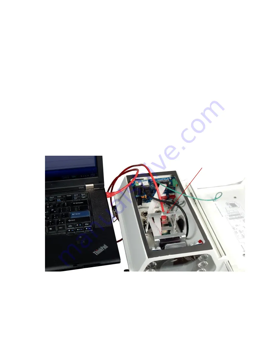
4.3 Connect the setup computer to the camera
Position the setup computer next to the camera being aligned. Make sure that nothing interferes with
the camera’s view of the road.
Connect the setup computer’s network adapter directly to the camera. Configure your network
adapter for a static IP of 10.0.0.xx, with xx being anything but 65. This will put the computer on the
same subnet as the camera (as configured at the factory, the camera is set to 10.0.0.65).
Figure 17. Example of direct connection to the camera
Once the setup computer is connected, you can apply power to the Drive5 (24V DC). The I/O Board
has 4 LEDs to indicate the status of the heaters, power supply, and microcontroller (I/O Board setup
parameters). Appendix A shows the locations of these LEDs. Appendix B contains an explanation of
the meaning of the lights and the colors that indicate proper operation.
Disconnect internal camera
cable from here and plug in
patch cable from setup
computer.


