BM-141GE / BB-141GE
55
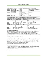
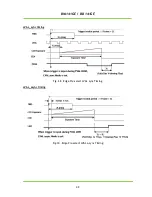
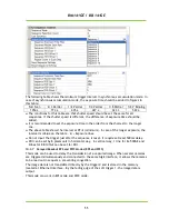
The following table shows the minimum trigger interval in synchronous accumulation mode. In
case of asynchronous accumulation mode, the exposure time should be added to figures in
this table.
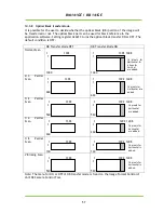
Full Scan
2/3 Partial
1/2 Partial
1/4 Partial
1/8 Partial
1/2 V Binning
1054 L
774 L
635 L
427 L
323 L
529 L
The conditions for this table are that shutter speed should be set the same for all
sequences. If the shutter speed is different, the difference of exposure time should be
added.
It is recommended to set the exposure time in the order from the shortest to the longer
one.
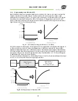
The above table shows the interval at PE=2 (minimum). In case of the longer exposure, the
interval is (Value on the table – 2) + Exposure lines.
Do not input the trigger just after the sequence is reset. It requires at least 500ms delay.
ROI can be set by 8 pixels unit in horizontal way. In vertical way, 1 line for B<-500GE and
2lines for BB-141GE can be set for ROI.
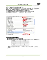
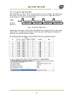
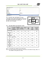
10.3.7 Delayed Readout EPS and PWC Modes (EPS and PWC)
This mode can be used to delay the transmission of a captured image. When several cameras
are triggered simultaneously and connected to the same GigE interface, it allows the cameras
to be read out in sequence, preventing congestion.
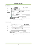
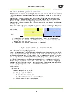
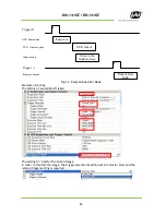
The image data is not transmitted directly by the trigger 0 and is stored in the memory
located at Ethernet Interface. By the falling edge of the soft trigger 1, the image data is
output.
This mode can work in EPS mode and PWC mode.
Содержание BB-141GE
Страница 5: ...BM 141GE BB 141GE 5 Change History 74 User s Record 75 ...
Страница 18: ...BM 141GE BB 141GE 18 Line Source 6 5 GPIO programming examples 6 5 1 Pulse generator setting sreen ...
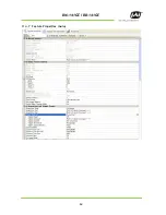
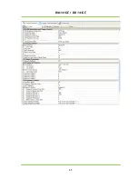
Страница 64: ...BM 141GE BB 141GE 64 11 4 7 Feature Properties Guru ...
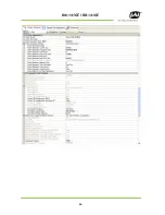
Страница 65: ...BM 141GE BB 141GE 65 ...
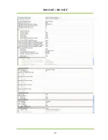
Страница 66: ...BM 141GE BB 141GE 66 ...
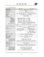
Страница 67: ...BM 141GE BB 141GE 67 ...

