background image

DCF-S-0126-2A (06.04)

Japan Aviation Electronics Industry, Ltd.

Connector Div. Production Engineering Dept.

日本航空電子工業株式会社コネクタ事業部生産技術部

Number

番号

T703580

Page

6

20

JAE Connector Div. Proprietary.
Copyright © 2020, Japan Aviation Electronics Industry, Ltd.

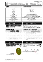
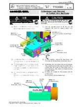
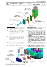
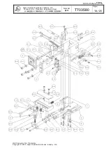
3.コンタクト挿入・取り外し

3.Attachment and Removal

of Contact into Applicator

注意

CAUTION

■アプリケータにコンタクトをセットする時、
又は取外す時は必ず電源プラグを抜いて下
さい。

In setting or removing contacts into the

applicator, disconnect the POWER plug from
the outlet.

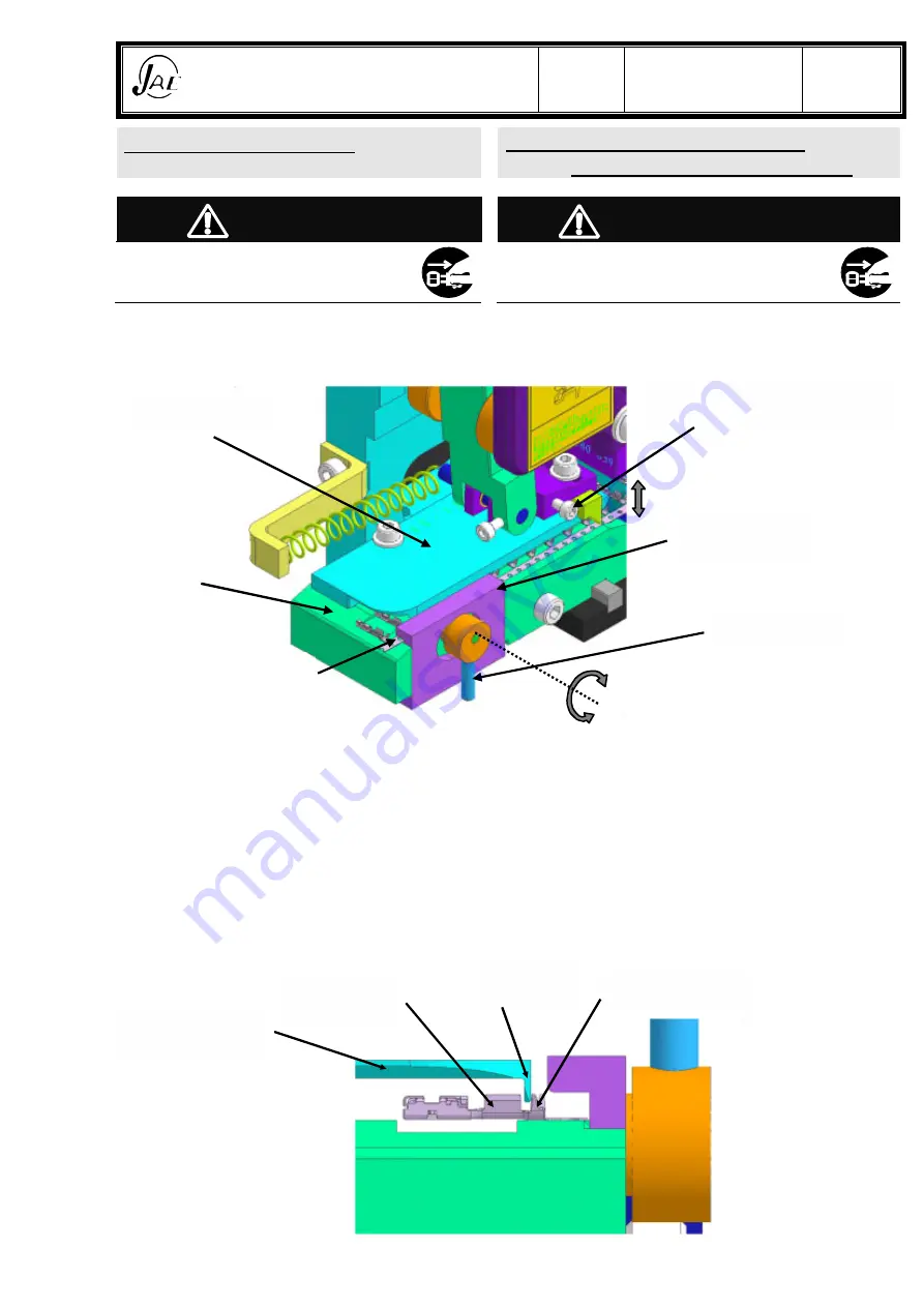
操作レバーを上側に回して下さい。レバーが下
側に有る場合は時計方向に回して下さい。

Turn the operation lever of the lift cum unit
upward.If

the

lever

is

placed

below,

turn

clockwise.

この状態で送り爪外しレバーを持ち上げてコン
タクトを送り台カバーと送り台の間に挿入しま
す。

In this condition, remove the feed finger, and
then insert contacts between feed plate cover.

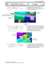
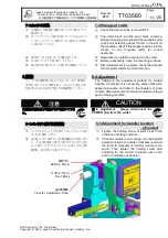
この時“手前側キャリアはコンタクト押えと送り台
の間に”又送り台カバーのガイド部が“コンタク
トの芯線バレルと被覆バレルの間に”入るように
して下さい。

At,that time, be sure to place the carrier between
“the contact hold and thecontact feed plate”.Also,
confirm that the guide of feed plate cover is
placed between “wire barrel of contact and the
insulation barrel”.

コンタクトはガイド部によって位置決めされてい
ます。
送り台カバーは不用意に取り外さないで下さ
い。

Contacts are guided for the location with the
location guide.
Do not remove the feed plate cover.

送り爪外しレバー

Lever for removal of feed finger

送り台カバー

Feed plate cover

コンタクト送り台

Contact feed plate

ガイド部

Guide

コンタクト押え

Contact Hold

操作レバー

Operation Lever

送り台カバー

Feed plate Cover

被覆バレル

Insulation barrel

芯線バレル

Wire barrel

ガイド部

Guide

6/20

Содержание 350-MX80-15

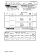
Страница 1: ...SSUED Production Engineering Dept Prepared Checked Approved PL Approved K KOIDE N SAKAI C YANOSAKI JAE Connector Div Proprietary Copyright 2020 Japan Aviation Electronics Industry Ltd Crimping Applica...

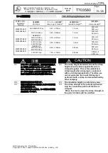
Страница 2: ...on means that there is a potentially dangerous situation that could lead to death or serious injury if the precaution is not followed CAUTION This indication means that there is a potentially dangerou...

Страница 3: ...s damaged please contact the store you purchased the tool or our sales office near you Be sure to take enough rest if you need to work with this tool for a long time Otherwise it may result in bodily...

Страница 4: ...of Insulation Height 8 6 6 Control of Crimp Height 9 7 7 Change of Crimper Anvil and Cutter 9 7 1 7 1 Change of crimper 9 7 2 7 2 Change of anvil 10 7 3 7 3 Change of cutter 11 8 8 Adjustment 11 8 1...

Страница 5: ...0 1mm CAUTION 700 03580 500 A safety cover is not included in the standard specifications If the crimping machine does not have a cover there is an optional safety cover 700 03580 500 2 2 Attachment...

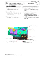
Страница 6: ...it upward If the lever is placed below turn clockwise In this condition remove the feed finger and then insert contacts between feed plate cover At that time be sure to place the carrier between the c...

Страница 7: ...first contact in the condution to be ready for crimping then put down the feed finger release lever Confirm for the top of feed finger to be inside the pilot hole then turn the contact hold lever to c...

Страница 8: ...crimp height in 0 03 mm steps with the crimp height adjustment disc Adjust the crimp height to match the wire used To adjust the crimp height turn the crimp height adjustment disc shown above clockwis...

Страница 9: ...Crimper Anvil and Cutter CAUTION In changing a crimper anvil or cutter disconnect the POWER plug from the outlet 7 1 7 1 Change of crimper Check that the machine is turned OFF M8 The wire crimper and...

Страница 10: ...tion Before reassembly clean the surfaces on the anvil block cutter block fixed cutter wire anvil and insulation anvil making sure all grit and foreign materials are removed Be sure to tightly press t...

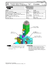
Страница 11: ...s complete check the front and rear movable cutters for correct motion 8 8 Adjustment The follwing is the adjustment method for contact location If adjustment is necessary please follow the applied pr...

Страница 12: ...t back adjustment screw fixing screws Loosen the feed finger screw If you turn the front back adjustment screw clockwise the contact feed plate moves to the back side Conversely turning it countercloc...

Страница 13: ...r Holder Operation Area Grease Lightly coating Once a week For Applicator Transfer Related Area Feed actuating Lever Feed Lever Knob Area 90 Turbine Oll 90 1 2 One or two drops per week For Roller Rol...

Страница 14: ...q 1 15 MX80P10K4F1 MX80S08K4F1 AESSX0 3 1 4 FLRY A0 35sq 1 25 FLRY B0 35sq 1 3 FLRY A0 5sq 1 5 FLRY B0 5sq 1 5 MX80P08K3F1 MX80S08K3F1 FLRY A0 75sq 1 8mm FLRY B0 75sq 1 8mm FLRY B1 0sq 2 0mm 10 2 10 2...

Страница 15: ...5sq FLRY B0 5sq 0 82 0 88mm 1 8mm 75N 75 min MX80P08K3F1 MX80S08K3F1 AESSX0 75 FLRY A0 75sq FLRY B0 75sq 0 90 1 00mm 2 25mm 90N 90N min FLRY B1 0sq 1 00 1 10mm 2 35mm 120N 120N min CAUTION 1 1 The cr...

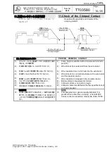
Страница 16: ...is extended from the wire barrel 3 3 Wire insulation does not intrude into the wire barrel 4 4 Wire strands do not protrude between the wire barrel and the insulation barrel 5 5 Wire insulation is wr...

Страница 17: ...Aviation Electronics Industry Ltd Connector Div Production Engineering Dept Number T703580 Page 17 20 JAE Connector Div Proprietary Copyright 2020 Japan Aviation Electronics Industry Ltd 12 12 Blown U...

Страница 18: ...6 2A 06 04 Japan Aviation Electronics Industry Ltd Connector Div Production Engineering Dept Number T703580 Page 18 20 JAE Connector Div Proprietary Copyright 2020 Japan Aviation Electronics Industry...

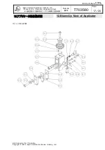
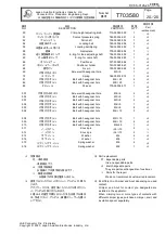
Страница 19: ...8 1 19 Pivot block 743 03344 019 1 20 Lift cam unit 700 03004 020 1 21 Key 723 03004 021 1 22 Roller pin 704 03004 022 1 23 Roller 711 03004 023 1 24 Feed actuating cam 741 03006 024 1 25 Crimper hold...

Страница 20: ...lt with hexagonal hole M8 25 1 89 PL PL seal 775 09004 011 1 501 Screw with hexagonal hole M4 4 4 502 Bolt with hexagonal hole M3 5 1 503 Bolt with hexagonal hole M3 8 2 504 Bolt with hexagonal hole M...

Страница 21: ...Mouser Electronics Authorized Distributor Click to View Pricing Inventory Delivery Lifecycle Information JAE Electronics C2777 350 MX80 15...

Отзывы: