background image

SERVICE MANUAL FOR SXG323&326

36

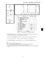
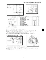
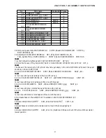
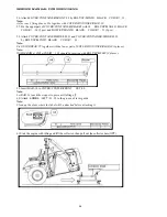
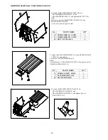
56. Attach COVER/CONTAINER/FRONT ,29 by BOLT/SP/M8X20

 BLACK  COLOR

 ,33. 

Note:


As for rear 3 fixing places, Fix together with COVER/CONTAINER/REAR ,30. 

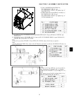
57. Fix the upper part of COVER/CONTAINER/REAR

 with 34  BOLT/SP/MAX40

 BLACK  

COLOR

    ,34 (2 pcs) and BOLT/SP/MAX20

 BLACK  COLOR

  , 33 (3 pcs). 

 
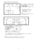
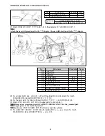
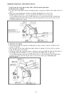
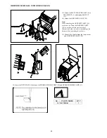
58. Attach COVER/CONTAINER/SIDE/LH ,31 and COVER/CONTAINER/SIDE/RH ,32 

  by BOLT/SP/M8X20

 BLACK  COLOR

  ,33. 

Note:


Fix GUIDE/REAR ,75 together with the lower part of COVER/CONTAINER/REAR,30.(3places.) 

Note:


WASHER/

凢凫


凤凪


凢凥凥処

    ,101 should be inserted with BOLT/SP/M8X40 (2 places). 


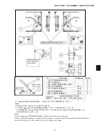
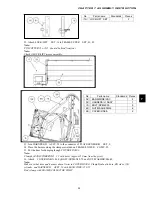
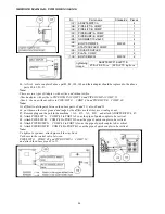
59. Insert BAR ,18 to COVER/CENTER/FRONT  SET ,88. 

Note:  

Let BAR ,18 touch the stopper to prevent it falling off. 

60. Attach 

凾凳凴凷凾

  /

凾击凸分

  /

  ,58 to the groove of lever guide. 

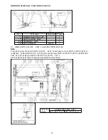
Note:


Clean up the place where the label will be attached before attaching it. 


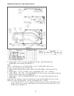
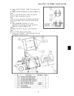
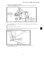
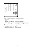
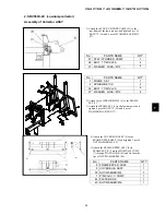
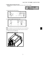
61.Start the engine with idling and lift the collector, then pull out the collector base(OPT). 


Содержание SXG323

Страница 1: ...LAWN MOWERS MOWER DECKS COLLECTORS SCMB48 SCMA54 SBC550X 600X ...

Страница 2: ...parts of a machine to new condition In discussion of each component part it is assumed that a complete overhaul is being performed consequently complete disassembly and reassembly are outlined The machine is relied upon to decide how far disassembly must be carried out when complete overhaul is not required Study unfamiliar service procedures thoroughly and understand them clearly before attemptin...

Страница 3: ...LECTRICAL ACCESSORIES 127 MOWER DECKS CHAPTER 1 FOR SAFETY LABELS 5 CHAPTER 2 SPECIFICATIONS 7 CHAPTER 3 ATTACHING AND DETACHING THE MOWER DECK 9 CHAPTER 4 MOWER OPERATION 11 CHAPTER 5 INSPECTION AND MAINTAINANCE OF MAJOR PARTS 17 CHAPTER 6 DISASSEMBLY AND REASSEMBLY OF GEAR BOX 25 CHAPTER 7 INSPECTION OF MOWER DECK SCMA TYPE 29 CHAPTER 8 TROUBLESHOOTING 33 COLLECTORS CHAPTER 1 SAFETY LABELS 5 CHA...

Страница 4: ...ISEKI LAWN MOWERS SXG323 326 ISEKI LAWN MOWERS SXG323 326 CHAPTER 1 CHAPTER 2 CHAPTER 3 CHAPTER 4 CHAPTER 5 CHAPTER 6 CHAPTER 7 CHAPTER 8 CHAPTER 9 CHAPTER 10 CHAPTER 11 CHAPTER 12 CHAPTER 13 ...

Страница 5: ......

Страница 6: ...BLOCKS 20 2 1 REMOVAL OF THE MOWER DECK 20 2 2 DETACHING THE COLLECTOR 21 2 2 1 DETACHING THE HIGH DUMP COLLECTOR 21 2 2 2 DETACHING THE LOW DUMP COLLECTOR 21 2 3 REMOVAL OF MAJOR FUNCTIONAL COMPONENTS 22 2 3 1 REMOVAL OF FENDER WING PANEL 22 2 3 2 REMOVAL OF FLOOR STEP COVER AND FUEL TANK 22 2 3 3 REMOVAL OF STEERING HEEL METER PANEL 23 2 3 4 REMOVAL OF RADIATOR 23 2 3 5 REMOVAL OF ENGINE 24 2 3 ...

Страница 7: ...ction nozzles 36 2 4 2 Inspection of oil tightness of valve seats 37 2 4 3 Spraying condition of injection nozzle 37 2 4 4 Inspection and adjustment of injection timing 37 2 5 COMPRESSION AND UNLOADED IDLING SPEEDS 39 2 5 1 Inspection of compression 39 2 5 2 Inspection and adjustment of the idling speeds 39 2 6 INSPECTION OF WATER PUMP 39 2 6 1 Inspection of the pump and pulley 39 2 6 2 Inspection...

Страница 8: ...3 OIL FILTER 68 1 4 EXPLODED VIEW OF OIL PUMP 69 2 REMOVAL DISASSEMBLY INSPECTION AND RE INSTALLATION OF OIL PUMP 70 2 1 REMOVAL OF OIL PUMP 70 2 2 DISASSEMBLY OF OIL PUMP 70 2 3 INSPECTION 70 2 4 INSTALLATION OF OIL PUMP 71 3 OIL FILTER 71 3 1 REMOVAL OF OIL FILTER 71 3 2 INSTALLATION OF OIL FILTER 71 CHAPTER 6 COOLING SYSTEM 73 1 COOLING SYSTEM DIAGRAM 73 2 THERMOSTAT 73 2 1 REMOVAL OF THERMOSTA...

Страница 9: ... MECHANISM GE type 88 4 BRAKE SYSTEM DISASSEMBLY 90 5 PRECAUTIONS FOR REASSEMBLY 90 6 BRAKE ADJUSTMENT 90 7 DIF LOCK ADJUSTMENT 91 CHAPTER 9 REAR AXLE 93 1 CONSTRUCTION 93 CHAPTER 10 HYDROSTATIC TRANSMISSION 95 1 CONSTRUCTION AND NAMES OF MAJOR COMPONENTS 95 2 OPERATING DIAGRAM OF HST 96 3 FUNCTION 97 3 1 VARIABLE TYPE PUMP 97 3 2 FIXED TYPE MOTOR 98 3 3 VALVES 98 4 DISASSEMBLY AND REASSEMBLY 100 ...

Страница 10: ...erated 122 3 MAJOR TROUBLES AND CAUSES AND COUNTERMEASURES 123 CHAPTER 13 ELECTRICAL ACCESSORIES 127 1 ELECTRICAL COMPORNENS AND WIRE HARNESS 127 2 WIRING DIAGRAM E TYPE 129 3 WIRING DIAGRAM GE TYPE 130 4 STARTER 131 4 1 CONSTRUCTION 131 4 2 REMOVAL AND DISASSEMBLY OF STARTER 132 4 3 INSPECTION OF COMPONENTS 132 4 4 REASSEMBLY OF STARTER 135 4 5 INSPECTION OF THE STARTER AFTER REMOVAL FROM THE TRA...

Страница 11: ...SERVICE MANUAL FOR SXG323 326 10 ...

Страница 12: ...umber 4 Production year Fig 1 2 A Model name plate B Engine plate C Punched model name and serial number on the right side of the chassis SXG323 H000001 b Engine model name and serial number The engine name is cast into the left hand side wall of the cylinder block The serial number is punched into the left hand side wall of the cylinder block Fig 1 3 1 Model 2 Displacement 3 Production serial num...

Страница 13: ...Capacity 21 liters 4 6 imp gal Transmission Main transmission HST Hydrostatic transmission Rear axle Chain drive Travel Forward 0 16 5 km h 0 10 3 mph 0 14 5 km h 0 9 mph Speeds Reverse 0 10 km h 0 6 3 mph Wheel base 1450 mm 57 1 in 1365 mm 53 7 in Wheel Tread Front 930 mm 36 6 in 910 mm 35 8 in Rear 860 mm 33 9 in Driving system 2WD Steering system Power steering Brake system Dry internal shoe ex...

Страница 14: ...CHAPTER 1 GENERAL INFORMATION 13 1 3 EXTERIOR VIEW Fig 1 4 ...

Страница 15: ...n replace after every 200h Suction filter Clean after initial 50h and then replace after every 200h Chain case Replace after initial 50h and then after every 200h maintain the specified level Brake pedal play c 20 to 30 mm 0 8 to 1 2h Steering wheel c Check after every 300h There should be no abnormality Ball joints of steering system linkage c Check after every 300h Loose ball joints should be re...

Страница 16: ... oil SAE80 1 1 0 24 5 Chain case LH Gear oil SAE80 1 1 0 24 6 Centre pivot Grease As required 7 Knuckle arms Grease As required 8 Cylinder ball end Grease As required 9 HST pedal hub Grease As required 10 Brake shaft Grease As required 11 HST link hub Grease As required 12 Brake shaft ÚOnly G type Grease As required 13 Mower link Grease As required 14 Fuel tank Diesel fuel 21 4 62 Oil fillers Oil ...

Страница 17: ...SERVICE MANUAL FOR SXG323 326 16 ...

Страница 18: ...erformance 1 2 PRECAUTIONS TO BE FOLLOWED WHEN INSTALLING COMMON PARTS a Roller or ball bearings When a bearing is fitted in by the outer race use an installer which is specially designed to push only the outer race and vice versa The installer must be designed to install the bearing on the shaft in a parallel position When installing a bearing which appears the same on both sides install it so th...

Страница 19: ...rts where much force is applied should be retained with wire f Cotter pins Split pin When installed cotter pins should be bent securely at the ends as shown in the figure Fig 2 3 g Bolts and nuts Special bolts are installed at several locations so be sure not to interchange them other bolts Bolts and nuts should be tightened to their specified torque with a torque wrench When locking the bolts or ...

Страница 20: ...ned evenly with bolts Adhesive coated surfaces should be installed within 30 minutes after application of the adhesive The contact surfaces should be flawless and free from foreign matter and especially from grease before application of the adhesive Contact surfaces of the sleeve metal support and front transmission case Contact surfaces of the hydraulic control leve guide and cylinder case Precau...

Страница 21: ...position Fig 2 4 3 Disconnect the universal joint of the front drive shaft from the lawn mower Fig 2 5 4 Disconnect the linkage from the mower deck Fig 2 6 5 Dismount the front linkage from the mower deck Fig 2 7 6 Start the engine and raise the mower linkage the lift lever 7 Turn the steering wheel to the right until the stopper 8 Turn the key switch OFF 9 Depress the discharge cover 10 Remove th...

Страница 22: ...right and left lift fulcrum pin 7 Set the collector lowest position by using lift and Push the lawn mower forward with using unload lever in the step Fig 2 9 Fig 2 10 2 2 2 DETACHING THE LOW DUMP COLLECTOR 1 Set the collector lowest position by using lift and dump lever 2 Remove the hose from dump cylinder 3 Separate the connection of grass limit sensor and safety switch wiring it is located in ri...

Страница 23: ...tor and mower deck 3 Remove the height adjust dial 4 Pull the pins of fender out and remove the fender Fig 2 12 Fig 2 13 Important The negative battery cable should be disconnected ahead of time to prevent short circuit 2 3 2 REMOVAL OF FLOOR STEP COVER AND FUEL TANK 1 Remove the center cover of step Fig 2 14 2 Remove the cover of steering column Fig 2 15 3 Remove the HST pedal and step Fig 2 16 ...

Страница 24: ... OF STEERING HEEL METER PANEL 1 Remove the steering wheel Fig 2 18 2 Disconnect the wire harness from meter panel 3 Remove the meter panel Fig 2 19 2 3 4 REMOVAL OF RADIATOR 1 Drain the coolant in radiator 2 Disconnect the radiator hose from engine 3 Disconnect the fan cover from radiator 4 Remove the radiator Fig 2 20 ...

Страница 25: ...nd radiator hose from engine 4 Disconnect the wire harness from engine 5 Separate the fuel hose from engine Fig 2 22 6 Disconnect the front PTO belt from engine Fig 2 23 7 Detach the engine from bracket Fig 2 24 2 3 6 REMOVAL OF REAR AXLE CASE 1 Remove the rear tyre 2 Drain the oil in rear axle case Fig 2 25 3 Detach the rear axle case from transmission case and chassis Fig 2 26 ...

Страница 26: ...control valve and pipe 4 Disconnect the brake linkage from transmission case 5 Disconnect the drive shaft from transmission case 6 Disconnect the HST linkage from transmission case Fig 2 28 7 Detach the transmission case from bracket Fig 2 29 2 3 8 REMOVAL OF FRONT AXLE CASE AND STEERING CYLINDER 1 Disconnect the hose of steering cylinder 2 Remove the steering cylinder Fig 2 30 3 Remove the pin of...

Страница 27: ... the right or to the left 2 Install the front PTO and related parts Install the PTO pulley and shaft Set the belt and tension pulley Install the stopper and cover 3 Install the driver shaft 4 Install fuel pipes Install the pipes on the injection pump Install the fuel return pipes on the nozzles 5 Connect wire harness Glow plug terminals Thermometer Oil pressure switch Starter Alternator Fuel cut o...

Страница 28: ...nt level is lowered due to evaporation maintain the level by adding water not by using an antifreeze solution When the coolant level is lowered due to leaks maintain the level by adding an antifreeze solution of the same mixing ratio Take care not to spill antifreeze on painted parts 3 INSPECTION FOR RADIATOR WATER LEAKS Water leaks are liable to occur at the fitting portion between the upper tank...

Страница 29: ...with pressurized water be sure to apply it at a right angle to the cores Slanted applications might deform their cooling fins 5 VISUAL INSPECTION OF THE EXTERIOR PARTS When the radiator exterior is corroded cracked or badly damaged and the radiator core fins are crushed or damaged replace the radiator Also replace dam aged or fatigued water hoses Retighten loose hose clamps securely if water is le...

Страница 30: ...compressed air not exceeding 200 kPa 30 psi from the inside of the element remove loose dirt grass chaff etc Be careful not to damage element pleats with air flow If the element is coated with oil or soot a Prepare solution of warm water and nonfoam ing detergent b Soak the element for thirty minutes c Agitate the element in solution until oil and soot are loosened d Rinse the element until rinse ...

Страница 31: ...ent sediment bowl and O ring Examine the small O ring in the filter head and replace as necessary 4 AIR BLEEDING PROCEDURE a Turn key switch ON b Fill the fuel tank c Turn the fuel valve 1 to ON d Loosen the air bleeding screw 2 and let air bubbles out e Loosen the air bleeding screw of the fuel injec tion pump and let air bubbles out of the pump Caution Fuel emitted from loosened injection lines ...

Страница 32: ...tor and water passages Adjust injection timing Clean radiator exterior Inspect cylinder head and replace cylinder gasket Over cooling Poor thermostat Excessive low atmospheric temperature Replace Decrease area of radiator working by masking radiator Loss of coolant Leaking radiator Loosely clamped or broken water hose Fatigued pressure valve spring Leaking water pump Water leakage through cylinder...

Страница 33: ...SERVICE MANUAL FOR SXG323 326 32 ...

Страница 34: ...sel fuel Fuel injection system Fuel injection pump Bosch PFR type pump Model ND PFR3M marking 6264 Plunger dia x stroke mm in 5 75X7 0X 0 23X0 28 Injection nozzle Throttle type Governor Centrifugal all speed governor Lubrication system Forced lubrication Oil pump Trochoid type Valve timing Intake Opening 10 BTDC Closing 46 ABDC Exhaust Opening 46 BBDC Closing 10 ATDC Valve clearance mm in 0 25 0 0...

Страница 35: ...SERVICE MANUAL FOR SXG323 326 34 1 2 PERFORMANCE CURVES 1 SXG326 E3112 G07 Fig 4 1 2 SXG323 E3112 G06 Fig 4 2 ...

Страница 36: ...block using a cartridge wrench b INSTALLATION OF OIL FILTER Inject a small amount of engine oil into the car tridge Apply engine oil to the O ring of the cartridge Tighten the cartridge by hand until the O ring comes into contact with the cylinder block sur face and then give it three fourth turn After fill ing with new oil operate the engine more than three minutes Then check for oil leaks 2 2 IN...

Страница 37: ... stroke use height difference among the push rods as a criterion for judgment When the heights of the push rods No 1 2 3 and 6 viewed from the fan are about 5 mm lower than those of No 4 and 5 the piston in No 1 cylinder is at TDC in compres sion stroke NSERT A FEELER GAUGE OF A SPECIFIED THICK NESS AND ADJUST THE CLEARANCE WITH THE ADJUSTING SCREW Specified valve clearance cold 2 4 INSPECTION AND...

Страница 38: ... NSPECTION AND ADJUSTMENT OF INJECTION TIMING Confirmation of injection timing using No 1 cylinder 1 Bring the piston in No 1 cylinder to TDC in com pression by aligning the marking on the crank shaft pulley with the one on the timing gear case turning the crankshaft by hand Note Be sure not to take TDC in exhaust for that in compression by checking for the opening and closing of the valves 2 Remo...

Страница 39: ... spring and stopper Then re tighten the delivery holder to the specified torque 11 Install the injection pipe and tighten the nut to the specified torque Note Supply fuel only when fuel injection timing is measured only for operation 6 It is impossible to measure the fuel injection tim ing by turning the crankshaft in reverse counter clockwise viewed from the fan During this operation be sure to k...

Страница 40: ...nozzle for the cylinder whose compression is to be measured Other nozzles should be left installed Caution When cranking the engine take care not to touch rotating parts NSPECTION AND ADJUSTMENT OF THE IDLING SPEEDS 1 Check for idling speeds 2 When the measured value deviates from the specified value correct with an adjusting bolt 2 6 INSPECTION OF WATER PUMP NSPECTION OF THE PUMP AND PULLEY Check...

Страница 41: ...n 0 2 mm 0 008 in replace the pump assembly 2 7 INSPECTION OF THERMOSTAT Inspection of activating temperatures at which the valve starts to open and opens fully Put the thermostat in water and heat the water gradually by stirring Check for the temperature at which the valve starts to open and that at which the valve opens fully 3 ENGINE BODY 3 1 CYLINDER HEAD IG XPLODED VIEW OF CYLINDER HEAD ...

Страница 42: ...he oil pipe 5 Removal of the rocker shaft assembly 6 Removal of the push rods 7 Removal of the water by pass hose 8 Removal of nozzles Remove the cap Remove fuel return pipes Draw out the nozzle along with the gasket Note Be careful to keep the nozzle free from dust 9 Removal of glow plugs 10 Removal of the cylinder head Loosen the cylinder head bolts in the sequence shown in the figure After the ...

Страница 43: ...bon deposit from the bottom surface of the cylinder head Inspect the bottom surface and inlet and exhaust ports using COLOR CHECK 2 Inspection of the cylinder head for distortion Measure the flatness of the bottom surface of the cylinder head by putting a straight rule diagonal ly across the four corners on the bottom face and check for clearance with thickness gauges When the distortion exceeds t...

Страница 44: ...new valve guide ahead of time Press in so that the distance from the cylinder head top to the valve guide end becomes 7mm After installation correct the bore diameter of the valve guide to the specified value by ream ing 5 Inspection and correction of valve seats Check for valve contacting width and depress sion When the contact width is wider than specified correct with a 45 valve seat cutter Whe...

Страница 45: ... free length of each valve spring with calipers Put a spring upright on a surface table and meas ure deviation from vertical 8 Inspection of intake and exhaust manifold con tact surfaces for flatness Measure flatness with a straight rule and thick ness gauges IG 3TANDARD VALUE 5SABLE LIMIT MM MM MM MM NLET VALVE XHAUST VALVE 3TANDARD VALUE 5SABLE LIMIT MM MM 6ALVE THICKNESS IG 3TANDARD VALUE 5SABL...

Страница 46: ...n of the rocker arm shaft for wear Measure diameter at four points where the shaft bears respective rocker arms When wear is in excess of the usable limit replace the shaft 4 Inspection of the clearance between the rocker arms and rocker arm shaft Measure the bore diameter of each rocker arm and calculate the difference from the diameter of the rocker arm shaft When the difference exceeds the usab...

Страница 47: ...eplace excessively worn rods with new ones Check push rods for bending Place a rod on a surface table and measure bend ing with thickness gauges 34 4 4 9 2 1 Installation of the cylinder head Clean the bottom surface of the cylinder head and the top surface of the cylinder block Drive in dowels Insert tappets Put a new gasket with its TOP mark turned upward A gasket of different models has a diffe...

Страница 48: ... lastly to the following torques Fig 4 43 2 Installation of the glow plugs 3 Installation of the injection nozzles Be sure to use new packing and tighten the noz zles to the specified torque Fig 4 44 4 Installation of the leak hoses Fig 4 45 5 Installation of the push rods Fig 4 46 6 Installation of the rocker arm assembly Loosen all rocker arm adjusting screws Install the rocker arm assembly and ...

Страница 49: ... cooling fan Remove the fan belt Remove the crankshaft pulley Remove the alternator Remove the injection pump cover and then remove the starting spring setting spring and control link from the rack Fig 4 49 sure to adjust the valve clearances 10 Installation of the head cover Note The head cover seal and gasket is made of rubber so take care not to tighten the head cover exces sively Remove the re...

Страница 50: ...EAR CASE Install the idle gear Apply oil to the bore surface of the idle gear and install taking care to align the timing marks with those of other gears Fig 4 53 Install the gear case Fig 4 54 Connect the rack of the injection pump and the control link with a setting spring After installa tion confirm their smooth working by moving the rack several times Install the starting spring Take care not ...

Страница 51: ...SERVICE MANUAL FOR SXG323 326 50 3 3 CYLINDER BLOCK 3 3 1 EXPLODED VIEW Fig 4 55 ...

Страница 52: ...e water pump spacer 11 Remove the oil filter 12 Remove the oil pan and oil strainer 13 Clean the cylinder bores of carbon deposit Remove carbon deposit from the upper part of the cylinder bore with a scraper taking care not to damage the cylinder walls Fig 4 58 14 Removal of the pistons and connecting rods Remove the nuts which tighten the connecting bearing cap Remove the piston connecting rod as...

Страница 53: ...ylinder block for damage Check for damage visually Use COLOR CHECK if necessary to check for cracks and other damage Repair damage if possible or replace Inspect the cylinder block top surface for flat ness Check the top surface for distortion with a straight rule and thickness gauges in diagonal ways as shown in the figure Fig 4 62 If distortion exceeds the usable limit correct on a surface grind...

Страница 54: ... and in three levels at a b and c differ less than 0 02 mm 0 0008 in from each other Fig 4 64 Fig 4 65 2 Inspection of the crankshaft Check the crankshaft journals for oil clearance a Clean the journals and bearings b Install the upper bearings and crankshaft on the cylinder block c Put plasti gauge over the journal width Fig 4 66 d Install the bearings on respective bearing caps Install the assem...

Страница 55: ...clear ance a Clean the crankshaft pins connecting rod big ends and bearings b Place plasti gauge over the pin width Fig 4 68 c Tighten the bearings on the connecting rods to the specified torque Fig 4 69 Note Hold the crankshaft securely so as not to turn while tightening d Loosen the tightening bolts and remove the con necting roil bearing caps carefully e Measure the most stretched parts of the ...

Страница 56: ... of the flywheel Check the friction surface for cracks and other damage If defective correct or replace with a new flywheel Check the ring gear teeth for excessive wear and other damage If defective replace the ring gear with a new one Fig 4 72 Replacement of the ring gear Hammer the circumference of the ring gear evenly via a holding rod to remove the ring gear Fig 4 73 Heat up a new ring gear wi...

Страница 57: ...e the bore diameter of each bearing And calculate the difference between the cam journal diameter and bearing bore diameter Clearance between journal and bearing If the clearance exceeds the usable limit replace the camshaft with a new one Fig 4 78 Thrust play of the camshaft Install the thrust plate and cam gear on the camshaft Push the thrust plate fully against the cam gear and measure the clea...

Страница 58: ...block and the outer diameter of each tappet Then calculate the difference Replace the tappets which have clearances in excess of the usable limit 3 3 4 INSPECTION OF PISTONS AND CON NECTING RODS Push a piston ring into the cylinder using a pis ton as a pushing tool to a point past the position where the ring would be during operation i e to the lower end of the cylinder wall Fig 4 81 Measure the g...

Страница 59: ...sive play in the hole at room temperature replace the piston or the pis ton pin Inspection of the clearance between the connect ing rod small end and piston pin Calculate the difference between the bore in the small end and piston pin diameter When the clearance exceeds the usable limit replace the connecting rod or the piston pin Oil ring No 1 compression ring No 2 compression ring Standard value...

Страница 60: ...in hole Set the piston and the connecting rod so that the front mark on the piston and ISEKI marking on the connecting rod are turned in the same direc tion Apply engine oil to the piston pin and push it into the hole by hand Fig 4 89 Install the other snap ring securely in the groove Fig 4 90 2 Installation of piston rings Install the rings using a piston ring expander with their T marks turned u...

Страница 61: ...AFT 1 Install the upper bearings which have oil grooves or oil holes in cylinder block Note Bearings and bearing fitting surfaces on the cyl inder block should be free from any foreign ma tter The projection of each bearing should be se curely seated in its notch in the cylinder block Fig 4 93 2 Apply engine oil to upper bearing surfaces and bring the crankshaft in contact with them Fig 4 94 3 Ins...

Страница 62: ...ces Clean the cylinder bores and crankshaft and apply engine oil to them Set the crankshaft at BDC Turn the front mark on the piston head towards the front and make sure that the piston ring gaps are 120 apart from each other Then insert the piston connecting rod assembly compressing the piston rings with a piston ring compressor into the cylinder until the connecting rod bearing comes into contac...

Страница 63: ...TRAINER AND OIL PAN Install the O ring in the groove in the hole for oil strainer installation Apply engine oil to the outer surface of the strainer pipe and install it by turning to avoid dislocation of the O ring Fig 4 101 Note Be careful not to damage the O ring 3 3 10 INSTALLATION OF REAR PLATE AND FLYWHEEL Installation of the rear plate Set the rear plate guided by the straight pins and tight...

Страница 64: ...ue Fig 4 104 Install key on the crankshaft Install the crankshaft gear on the crankshaft with the side bearing the front mark turned forward Apply engine oil to the camshaft bearing parts and install the camshaft assembly Then tighten to the specified torque Fig 4 105 Sub assemble the pump cam and the thrust plate in advance paying attention to thrust plate direc tion Fig 4 106 Insert the starting...

Страница 65: ... those of other gears Fig 4 109 Installation of the injection pump Tighten the bolts to the specified torque in sequence as shown in the figure Note Remember to install adjusting shims Fig 4 110 Installation of the oil pan Apply liquid gasket THREE BOND1207D to the cylinder block surface in shape of a string of φ3 3 5 mm φ0 12 0 14 in as illustrated Then install the oil pan and tighten to the spec...

Страница 66: ...page 49 Install the cylinder head referring to page 46 Install the water pump spacer Install the water pump with new packing and tighten to the specified torque Fig 4 113 Install the water by pass hose Install the generator Install the fan Set the fan belt on the fan pulley Install the spacer and the fan Specified torque 1 4 2 4 kgf m ...

Страница 67: ...SERVICE MANUAL FOR SXG323 326 66 ...

Страница 68: ...CHAPTER 5 LUBRICATION SYSTEM 67 5 1 GENERAL DESCRIPTION 1 1 LUBRICATION DIAGRAM Fig 5 1 CHAPTER 5 LUBRICATION SYSTEM ...

Страница 69: ...KH RLO SXPS LV IHG LQWR WKH UHOLHI YDOYH ZKHUH RLO SUHVVXUH LV PDLQWDLQHG D FRQVWDQW OHYHO E WKH UHOLHI YDOYH DQG GHOLYHUHG WKURXJK WKH RLO JDOOHU WR WKH RXWVLGH FLUFXPIHU HQFH FKDPEHU LQ WKH RLO I LOWHU 7KH RLO LV FOHDQHG ZKLOH SDVVLQJ WKURXJK WKH HOHPHQW DQG JRHV RXW WKURXJK WKH FHQWUDO SRU W SDVVLQJ WKURXJK WKH RLO JDOOHU DQG OXEULFDWHV WKH FUDQNVKDIW MRXU QDOV DQG RWKHU HQJLQH SDUWV Fig 5 3 Oi...

Страница 70: ...CHAPTER 5 LUBRICATION SYSTEM 69 5 1 4 EXPLODED VIEW OF OIL PUMP Fig 5 4 ...

Страница 71: ...H WKH RLO SXPS JHDU DQG FRYHU KHQ WKH LQQHU URWRU RU RXWHU URWRU LV Z RUQ RU GDPDJHG UHSODFH WKH SXPS DVVHPEO ZLWK D QHZ RQH OHDUDQFH RI WKH LQQHU DQG RXWHU URWRUV ZLWK WKH FRYHU KHQ WKH FOHDUDQFH H FHHGV WKH XVDEOH OLPLW UHSODFH WKH SXPS DVVHPEO Fig 5 6 0HDVXUH WKH FOHDUDQFH EHWZ HHQ WKH LQQHU URWRU DQG RXWHU URWRU KHQ WKH FOHDUDQFH H FHHGV WKH XVDEOH OLPLW UHSODFH WKH SXPS DVVHPEO Fig 5 7 0HDVXU...

Страница 72: ...OF OIL FILTER 5HPRYH WKH RLO I LOWHU FDUWULGJH IURP WKH F OLQGHU EORFN XVLQJ D FDUWULGJH ZUHQFK Fig 5 10 3 2 INSTALLATION OF OIL FILTER QMHFW D VPDOO DPRXQW RI HQJLQH RLO LQWR WKH FDU WULGJH SSO HQJLQH RLO WR WKH 2 ULQJ RI WKH FDUWULGJH Fig 5 11 7LJKWHQ WKH FDUWULGJH E KDQG XQWLO WKH 2 ULQJ FRPHV LQWR FRQWDFW ZLWK WKH F OLQGHU EORFN VXU IDFH DQG WKHQ JLYH LW WKUHH IRXUWK WXUQ IWHU ILOOLQJ ZLWK QHZ...

Страница 73: ...SERVICE MANUAL FOR SXG323 326 72 ...

Страница 74: ...move the radiator hoses Remove the water outlet Remove the thermostat 2 2 INSTALLATION OF THERMOSTAT Discard the removed O ring and install a new one 2 3 INSPECTION OF THERMOSTAT Inspection of activating temperatures at which the valve starts to open and opens fully Put the thermostat in water and heat the water gradually by stirring Check for the temperature at which the valve starts to open and ...

Страница 75: ...by pass hose Remove the water pump Remove the water pump spacer 3 2 INSTALLATION OF WATER PUMP Install the water pump spacer with new packing Install the water pump with new packing and tighten to the specified torque Remove the cooling fan and pulley Install the pulley belt and cooling fan 3 3 INSPECTION OF WATER PUMP Inspection of the pump and pulley Check the pump for noise or hitching by turni...

Страница 76: ...type The construction is the same as that of the 2 cylinder type except in cylinder number Fig 7 1 兟Specifications Pump type Element Pre stroke Rack stroke Allowable max speed NP PFR2MD60 1NP6 䪻 6 0 mm counter clockwise leading 12 mm 0 472 in 1 9 0 05 mm 0 075 0 002 in 10 mm 0 394 in Np 2750 rpm CHAPTER 7 FUEL SYSTEM ...

Страница 77: ...nations of the plunger and plunger arrel and the delivery valve and delivery valve seat must not be changed 兟Figures in parentheses following parts name in the text show reference numbers in Fig 7 2 or tool numbers 1 Pump housing 5 Plunger assembly 12 Delivery valve assembly 13 Delivery valve spring 16 Gasket 17 Delivery valve holder 20 O ring 30 Sleeve flange 31 Pin 32 O ring 37 Socket head bolt ...

Страница 78: ...he tightening bolts 2 2 DISASSEMBLY OF INJECTION PUMP 1 Remove snap ring 45 from pump housing 1 Fig 7 5 4 Remove plunger 5 and spring seat 52 NOTE Keep removed plungers in clean fuel in order of cylinders Fig 7 3 2 Push up tappet 40 and pull out pin 44 Fig 7 6 Fig 7 4 5 Pull out plunger spring 50 3 Pull out shim 53 along with the tappet Fig 7 7 6 Move the pin which is press installed in the contro...

Страница 79: ...ve control sleeve 77 along with spring seat 51 Fig 7 12 12 Pull out delivery valve spring 13 8 Fig 7 9 Remove four screws 66 which tighten the plate 13 Remove delivery valve assembly 12 along with gasket 16 Fig 7 10 9 Remove the plate 10 Remove control rack 60 Fig 7 13 14 Pull out the plunger barrel from each sleeve flange Assemble remove plunger barrels with respective plungers which have already...

Страница 80: ...k the pump housing for cracks wear or damaged screw threads If defective replace the housing 2 Tappets Fig 7 16 4 Replace a control sleeve whose recess where the brim of the plunger or the ball of PFR MD type is to be seated is abnormally worn 5 Plunger assembly 兟When the notched part in the plunger is damaged dis colored or worn replace the assembly of the plunger and plunger barrel Replace a tap...

Страница 81: ...very valve sufficiently in clean fuel While it is still wet after washing close the opening with a finger and push it in to see that it pushes back positively Fig 7 20 Fig 7 19 3 When installing the plunger into the plunger barrel be sure to turn the notch in the plunger in the op posite direction of the control rod towards the posi tioning pin of the plunger 7 Gaskets and O rings Be sure to disca...

Страница 82: ...by turning the control rod little by little Fig 7 25 兟Loosen the retaining nuts Use a box wrench or open end wrench of 22 mm 0 866 in NOTE Be careful not to loosen the hexagonal part 19mm 0 748 in of the holder body If done so the holder becomes disassembled Fig 7 23 3 2 INSPECTION OF INJECTION NOZZLES 6 Adjust the groove in the pin so it is in level using a screw driver and install the snap ring ...

Страница 83: ...ASSEMBLY AND WASHING OF INJECTION NOZZLES Fig 7 27 兟Removal of the packing ring Loosen the joint nut without removing the nozzle from the engine NOTE Take care not to damage the packing ring and the washer contacting surface of the nozzle holder 兟Hold the nozzle holder assembly in a vice by the hex agonal part 19 mm 0 75 in of the nozzle body with the nozzle turned upwards Then loosen the retainin...

Страница 84: ...of its smooth movement Slant the nozzle body by about 60 pull out the needle valve by about one third of its length and release it When it comes down smoothly it is normal Perform three tests with the needle valve turned by 120 at each test If the needle valve does not move smoothly replace the assembly of the needle valve and nozzle holder Fig 7 28 NOTE When installing the pressure pin and distan...

Страница 85: ...aptation device which will be explained later is installed on the tension arm The Angleichung pin end is in contact with the control link pin which is connected with the control lever A setting spring is installed at the connecting point of the control link and control rod to eliminate free play of the rod in direction of movement and to se cure the connection A starting spring is installed on the...

Страница 86: ... wrench which may cause fuel leakage 兟Place the packing ring in position and tighten the joint nut to the specified torque Specified torque 2 2 5 kgf兟m 兟Install the injection pipe and leak off pipe and tighten them to the specified torque Specified torque 2 5 kgf兟m or less ...

Страница 87: ...e the force of the governor spring and starting spring surpasses the centrifugal force and the thrust peace is pushed back Then the control rack is shift ed to increase fuel and thus restore engine speeds Engine speeds are maintained at a constant level in his way Fig 7 31 3 When the control lever is set in the full load posi tion tension of the tension spring is increased and the tension arm is i...

Страница 88: ...6 42 2 ENGINE HST UNIT BRAKE 12T 45T 23T 48T 11T 29T FRONT PTO OPTION 1750rpm at engine 2600rpm ENGINE HST UNIT BRAKE 12T 45T 23T 48T 11T 29T FRONT PTO OPTION 1750rpm at engine 2600rpm Fig 8 1 Fig 8 2 7 3 7 3 CHAPTER 8 TRANSMISSION AND RELATED PARTS ...

Страница 89: ...SERVICE MANUAL FOR SXG323 326 88 42 3 33 Fig 8 3 2 2 7 2 6 3 TYPE Fig 8 4 ...

Страница 90: ...WKH WUDQVPLVVLRQ FDVH DVV IURP WKH EUDFNHW Fig 8 5 6HSDUDWH WKH WUDQVPLVVLRQ FDVH IURP WKH 67 FDVH Fig 8 6 6HSDUDWH WKH WUDQVPLVVLRQ FDVH Fig 8 7 30 4 KHFN WKH LQSXW JHDU DQG EHDULQJ Fig 8 8 KHFN WKH GLIIHUHQWLDO JHDU Fig 8 9 KHFN WKH JHDUV DQG EHDULQJ Fig 8 10 ...

Страница 91: ...G LQQHU VXUI DFH RI WKH EUDN H GUXP VKRXOG EH IUHH IURP RLO RU GXVW 2 534 4 8 7 3 534 2 2 HSUHVV WKH EUDNH SHGDO XQWLO WKH VWRSSHU GMXVW WKH OHQJWK RI EUDNH URG VR WKDW GLVWDQFH RI VSULQJ LV PP IWHU DGMXVWLQJ WKH EUDNH URG EH VXUH WR FKHFN IUHH SOD RI EUDNH DUP DQG FRQILUP GLVWDQFH RI D VFUHZ LV ZLWKLQ PP KHFN WKH RLO VHDO DQG RWKHU JHDU 2 3934 3 33 9 5HPRYH WKH VQDS ULQJ Fig 8 11 5HPRYH WKH EROWV...

Страница 92: ...ABLE OF PARKING LEVER 1 Pull up the parking lever until 8 notch 2 Adjust the length of left and right brake rod so that each distance of spring of spring is 0 3mm 3 After releasing the parking brake be sure to check free play of brake cable 7 DIF LOCK ADJUSTMENT Fig 8 16 1 Make sure the Arm Diff 4 to move completely and fasten the adjusting plate 1 by the bolts 2 Fig 8 17 2 After re installing the...

Страница 93: ...SERVICE MANUAL FOR SXG323 326 92 ...

Страница 94: ... Drain the oil in the rear axle case Fig 9 2 2 Separate the rear axle case Fig 9 3 Fig 9 1 3 Remove the gear and chain and tension plate Fig 9 4 4 Detach the rear axle case from chassis 5 Remove the snap ring on the wheel shaft Fig 9 5 CHAPTER 9 REAR AXLE ...

Страница 95: ...G323 326 94 6 Remove the wheel shaft Fig 9 6 7 Remove the snap ring on the bearing Fig 9 7 8 Remove the bearing from the rear axle case Fig 9 8 9 Remove the snap ring on shaft Fig 9 9 10 Remove the shaft from case Fig 9 10 ...

Страница 96: ...䎳䏌䏑 䎋䎘䎕䎌 䎲䎐䏕䏌䏑䏊 䎋䎙䎌 䎳䏌䏖䏗䏒䏑 䎋䎕䎙䎌 䎲䎐䏕䏌䏑䏊 䎋䎗䎙䎌 䎥䏒䏏䏗 䎋䎘䎖䎌 䎳䏏䏘䏊 䎋䎚䎌 䎶䏋䏌䏐䎋䎓䎑䎜䎌 䎋䎕䎚䎌 䎪䏄䏖䏎䏈䏗 䎋䎗䎚䎌 䎵䏈䏏䏌䏈䏉 䏙䏄䏏䏙䏈 䎋䎛䎌 䎹䏄䏏䏙䏈 䏓䏏䏄䏗䏈䎋䏓䏘䏐䏓䎌 䎋䎕䎛䎌 䎳䏏䏘䏊 䎋䎜䎌 䎹䏄䏏䏙䏈 䏓䏏䏄䏗䏈䎋䏐䏒䏗䏒䏕䎌 䎋䎕䎜䎌 䎳䏏䏘䏊 䎋䎔䎓䎌 䎶䏋䏄䏉䏗䎋䏓䏘䏐䏓䎌 䎋䎖䎓䎌 䎲䎐䏕䏌䏑䏊 䎋䎔䎔䎌 䎶䏋䏄䏉䏗䎋䏐䏒䏗䏒䏕䎌 䎋䎖䎔䎌 䎲䎐䏕䏌䏑䏊 䎋䎔䎕䎌 䎤䏕䏐䎋䏗䏕䏘䏑䏑䏌䏒䏑䎌 䎋䎖䎕䎌 䎶䏑䏄䏓䎐䏕䏌䏑䏊 䎋䎔䎖䎌 䎷䏋䏕䏘䏖䏗 䏅䏈䏄䏕䏌䏑䏊 䎋䎖䎖䎌 䎶䏑䏄䏓䎐䏕䏌䏑䏊 䎋䎔䎗䎌 䎥䏄䏏䏏 䏅䏈䏄䏕䏌䏑䏊 䎋䎖䎗䎌 䎶䏑䏄䏓䎐䏕䏌䏑䏊 䎋䎔䎘䎌 䎱䏈䏈䏇䏏䏈 䏅䏈䏄䏕䏌䏑䏊 䎋䎖䎘䎌 䎲䏌䏏 䏖䏈䏄䏏 䎋䎔䎙䎌 䎥䏘䏖䏋 䎋䎖䎙䎌 䎲䏌䏏 䏖䏈䏄䏏 䎋䎔䎚䎌 䎥䏘䏖䏋 䎋䎖䎚...

Страница 97: ...SERVICE MANUAL FOR SXG323 326 96 2 OPERATING DIAGRAM OF HST Fig 10 2 ...

Страница 98: ...0 4 Pistons are housed in the cylinder block which is connected to the engine and revolves as the engine does while the slant board does not When the slant board and shaft are perpendicular to each other cylinder displacement volumes A and B do not vary so no delivery or suction takes place ...

Страница 99: ...SERVICE MANUAL FOR SXG323 326 98 Fig 10 5 Fig 10 6 ...

Страница 100: ...CHAPTER 10 HYDROSTATIC TRANSMISSION 99 10 Fig 10 7 ...

Страница 101: ...SERVICE MANUAL FOR SXG323 326 100 Fig 10 8 4 DISASSEMBLY AND REASSEMBLY ...

Страница 102: ...CHAPTER 10 HYDROSTATIC TRANSMISSION 101 10 4 3 ...

Страница 103: ...SERVICE MANUAL FOR SXG323 326 102 ...

Страница 104: ...pump side Remove the cylinder block assembly motor side Fig 10 11 2 Remove the cylinder block assembly Fig 10 12 Components of the cylinder block assembly Both blocks have the same components Cylinderblock 1 Pistons 9 Springs 9 Spring holders 9 Fig 10 13 3 Remove the slant board assembly which in cludes the swash plate and bushing from the case and then take out the thrust bearing bush and sliding...

Страница 105: ...ump shaft a Remove the four screws and take out cover pin and O ring from the case Fig 10 16 b Remove the snap ring and hit the end of the shaft with a plastic hammer as shown in the figure blow and extract the shaft from the case Fig 10 17 Removal of motor shaft a Remove the snap ring and pry off the bore plug with a conventional screw driver ...

Страница 106: ... out of the case Fig 10 19 6 Disassembly of the trunnion shaft a Remove the snap ring and hit the end of trunnion shaft with a plastic hammer as shown in the fig ure below in order to extract it out of the case b Remove the bearing Fig 10 20 7 Disassembly of the port block a Remove the plug for the check valve and take out the springs and poppets out of the port block b Remove the valve sub assemb...

Страница 107: ...SERVICE MANUAL FOR SXG323 326 106 4 5 CRITERIA FOR REPLACING WORN PARTS ...

Страница 108: ...EASSEMBLY 1 Reassembly of the trunnion shaft a Install the snap ring into the case Install the oil seal b Install the trunnion shaft assembly which is composed of the trunnion shaft sub assembly and the ball bearing Fig 10 22 c Install the washer and ball bearing and retain the shaft with the snap ring Fig 10 23 2 Reassembly of the shafts Assembly of the pump side shaft a Install the pump shaft as...

Страница 109: ... and thrust bearing a Install the thrust bearing into the case Install the thrust bearing with the side bearing no marking turned towards the pistons Fig 10 27 b Install the two bushes in the case c Install the sliding piece onto the trunnion shaft Fig 10 28 d Installl the thrust bearing onto the slant board assembly which includes the swash plate and bush Install the slant board so that the groov...

Страница 110: ...y with the copper alloy side turned towards you and install the valve plates Apply grease to the valve plate ahead of time to prevent it from falling The valve plate with two notches should be installed on the pump Fig 10 31 b Install the valve sub assembly Apply grease to the valve ahead of time to pre vent it from falling c Install the springs pins and gasket onto the case Apply grease to the sp...

Страница 111: ...SERVICE MANUAL FOR SXG323 326 110 Fig 10 33 e After being reassembled make sure that the shafts turn smoothly using an adjustable end wrench Fig 10 34 Fig 10 35 ...

Страница 112: ...Bore plug installation Note Press in the bore plug until its top sinks to 4 2 mm deep from the case surface Prepare pressing in jigs in accordance with the dimensions mentioned on the drawing Fig 10 37 c Swash plate slant board assembly Press the bush into the slant board so that the bush end becomes flush with the surface of the swash plate Fig 10 38 d Trunnion shaft assembly Fig 10 39 ...

Страница 113: ...nks to 12 5 mm below the case surface Fig 10 41 f Port block assembly As for the pressed in parts refer to paragraph g Fig 10 42 g Pressed in parts in the port block Note The oil seal should be installed with the dust lip turned outward Install the bearing until the end protrudes by 2 5 mm beyond the port block surface Prepare pressing in jigs in accordance with the dimensions mentioned on the dra...

Страница 114: ...force to the trun nion shaft than HST operating force 4 11 PRECAUTIONS AFTER INSTALLATION OF HST UNIT 1 STARTING a Fill the HST case with working fluid b After the installation of the HST system oper ate the control lever or pedal slowly several times in order to bleed the system of air com pletely When air bleeding is incomplete trapped air bubbles make noise Repeat the above air bleed ing operat...

Страница 115: ...t is very difficult to judge how oil has dete riorated visually a rule of thumb is given below Normally the oil should be replaced after the intial 50 hours of operaton and then every year before the new season begins when the machine is used for less than 250 hours or every 250 hours of operation As water and sludge will be deposited in the cir cuits and oil tank when replacing the working oil th...

Страница 116: ...set j Stop the engine and apply the parking brakes Tighten the adjust nut securely Fig 10 47 1 HST rod 3 Trunnion arm 2 Lock nuts k Next align both HST pedals in height by adjust ing the effective length of the HST rod with the two lock nuts Be sure to tighten the lock nuts securely after adjustment l Loosen the lock nut of the crank plate stopper bolt and screw in the bolt slightly to shorten the...

Страница 117: ...SERVICE MANUAL FOR SXG323 326 116 ...

Страница 118: ...K182 032 000 CYLINDER ASSY for MOWER LIFTING X A1 φ 6 φ 6 B2 A2 φ 6 φ 6 X X B3 A3 φ 6 φ 6 T P C PB 1728 508 270 VALVE 1S 2D ASSY ENG 2600rpm GEAR RATIO 31 34 0 912 INPUT LEFTHAND ROTATION CCW CHARGE FILTER P103 521 300 10μ COLLECTOR LIFT COLLECTOR OPEN HIGH PRESSURE RELEAF 22 6MPa 230kgf cm 2 21 5 cc rev 0 21 5 cc rev T B LOW PRESSURE RELEAF 0 49MPa 5kgf cm 2 φ1 3 φ0 5 K510 005 000 HST SXG 21 ASSY...

Страница 119: ...SERVICE MANUAL FOR SXG323 326 118 Pump port A Tank port B E port C Right port D Left port E A B C D E Fig 11 2 Steering control ...

Страница 120: ...or damage and wash undamaged and usable parts except for rubber parts in clean diesel fuel or kerosene Inspect all parts and repair or replace defective Fig 11 3 2 3 RELIEF VALVE FUNCTION This device functions as a flow distributor of the pressurized fluid from the pump and the built in relief vavel stabilises the pressure in the mini orbit roll It is installed on the mini orbit roll parts with ne...

Страница 121: ... support The filter cartridge is attached on the HST unit Bypass relief valve in the base Replace the cartridge with a new one after the initial 50 hours of operation and the after every 200hours of operation 6 0 6 5Mpa Relief pressure 61 2 66 3kgf cm2 1 5Mpa Opening pressure 1 5kgf cm2 ...

Страница 122: ...trol steering Left port E Right port D E port C Tank port B Pump port A E T P R L CYLINDER ASSY 32cc rev 6 0 6 5MPa 61 2 66 3kgf cm 2 P RELEAF PRESSURE STREERING ASSY CONTROLLER E PB T L R 1 CONSTRUCTION Fig 12 1 CHAPTER 12 POWER STEERING SYSTEM ...

Страница 123: ...CE MANUAL FOR SXG323 326 122 2 WORKING PRINCIPLE Fig 12 2 Fig 12 3 when the steering wheel is in neutral Fig 12 4 when the steering wheel is turned to right Fig 12 5 when the steering wheel is turned to left ...

Страница 124: ...CHAPTER 12 POWER STEERING SYSTEM 123 12 3 MAJOR TROUBLES AND CAUSES AND COUNTERMEASURES ...

Страница 125: ...SERVICE MANUAL FOR SXG323 326 124 ...

Страница 126: ...CHAPTER 12 POWER STEERING SYSTEM 125 12 ...

Страница 127: ...SERVICE MANUAL FOR SXG323 326 126 ...

Страница 128: ...CHAPTER 13 ELECTRICAL ACCESSORIES 127 13 1 ELECTRICAL COMPORNENS AND WIRE HARNESS 1 UE TYPE 2 UGE TYPE RELAYS FUSE Fig 13 1 Fig 13 2 Fig 13 5 Fig 13 3 Fig 13 4 Fig 13 6 CHAPTER 13 ELECTRICAL ACCESSORIES ...

Страница 129: ...SERVICE MANUAL FOR SXG323 326 128 3 ALL TYPE Engine Fig 13 7 Fig 13 8 Fig 13 10 Fig 13 9 Fig 13 11 ...

Страница 130: ...CHAPTER 13 ELECTRICAL ACCESSORIES 129 13 2 WIRING DIAGRAM E TYPE Fig 13 12 ...

Страница 131: ...SERVICE MANUAL FOR SXG323 326 130 3 WIRING DIAGRAM GE TYPE Fig 13 13 ...

Страница 132: ...CHAPTER 13 ELECTRICAL ACCESSORIES 131 13 Fig 13 14 4 STARTER ...

Страница 133: ...Remove the commutator end frame and an O ring 3 Removal of the starter housing Disconnect the starter housing from the magnet ic switch Remove the drive pinion Remove the idle gear and retainer with roller 4 Removal of the clutch assembly Remove the clutch assembly from the magnet switch 5 Removal of the steel ball and spring 6 Removal of the brush holder Lift up the brush spring and take out the ...

Страница 134: ...amage can be correct ed with sandpaper of 400 or higher no Inspect the commutator for run out with a dial gauge on a V block Measure the commutator diameter with vernier calipers Measure mica depth against segment top 4 Inspection of field coils for short circuit Inspect for continuity across the lead from termi nal C and field coil brush If there is continuity the coils are normal 5 Inspection of...

Страница 135: ...side of the brush holder If there is no continuity the brush holder is normal 9 Inspection of the clutch Inspect the gear for wear and damage Make sure that the gear locks when turned in diving direction and turns smoothly in the re verse direction There should be no hitching when the bearing is turned manually by applying some force to it with fingers It should not make abnormal noises when turne...

Страница 136: ...he armature Apply grease to the armature bearing and then install the armature on the starter yoke 2 Installation of the brushes and brush holder Lift up and hold the spring and install the brush Install the commutator end frame using an O ring 3 Installation of the starter yoke armature Install the starter yoke on the magnetic switch using an O ring 4 Installation of the steel ball and spring App...

Страница 137: ...revent damage 1 Pull in test Make sure the pinion is pushed out when the starter is connected as illustrated 2 Coil holding test In the state of the pull in test the gear should remain pushed out when the lead is disconnected from terminal C 3 Plunger return test In the state of the coil holding test the pinion should retract when the connection is removed as illustrated 4 6 PERFORMANCE TEST Note ...

Страница 138: ...m spinning Each value should be as shown below 4 7 INSTALLATION OF THE STARTER 1 Connect the wiring Connect the lead to terminal 30 and tighten it with the nut Install the connector on terminal 50 2 Install the starter on the engine 3 Connect the negative battery cable Voltage Current 8 0 V 230A or less at 1180 rpm or over Torque 0 65 kgf or over Fig 13 43 Fig 13 44 ...

Страница 139: ...SERVICE MANUAL FOR SXG323 326 138 Fig 13 45 Fig 13 46 5 ALTERNATOR 5 1 EXPLOTED VIEW SPECIFICATIONS AND PERFORMANCE CURVES ...

Страница 140: ...CHAPTER 13 ELECTRICAL ACCESSORIES 139 13 Fig 13 48 Fig 13 47 ...

Страница 141: ...e sult in serious damage in the end e Removal of the rectifier Remove the four screws which tighten the leads for the rectifier and stator Then the rectifier is removed f Removal of the brushes Remove the four nuts and bushes which tighten the drive end frame and rear end frame Then the brush assembly is removed Note When removing the bushes take care not to stretch the wire from the stator g Remo...

Страница 142: ...ress Note The bearing is a high speed type so be sure to use a specified one by ISEKI when replacing Never give it shock k Removal of the baring which is installed on the slip ring side Remove the bearing using a puller as illustrated 5 4 INSPECTION a Inspection of the rotor slip rings Measure the outer diameter of the rings If the measured value exceeds the usable limit replace with a new one Mak...

Страница 143: ...rings Noisy or hitching bearings should be replaced with new ones c Continuity test of the stator coils Check for continuity across respective coil ter minals with a tester If there is no continuity re place the stator f Insulation test of the stator coils Check continuity across one of the stator termi nals and stator core If there is continuity re place the stator g Inspection of the rectifier S...

Страница 144: ...ct resistance reading Consequently the diode should be considered normal when the resistance difference between the forward direction and reverse direction is large enough Never apply MQ range of the tester which may damage the diode h Inspection of the brushes Measure the length of the brush exposed above the brush holder If the length is less than the usable limit replace i Specified tightening ...

Страница 145: ...lator variable DC power supply voltmeter and a lamp as illustrat ed Keep SW1 and SW2 turned off Set the power supply at 12V Turn on SW1 Make sure that LI in place of the charge lamp is lit bright and L2 in place of the rotor coil is also lit Then turn on SW2 with SW1 on Make sure that LI is turned off and L2 remains lit When the power supply output is changed gradu ally from 12V until 14 5 0 6 at ...

Страница 146: ...the IC regulator 6 GLOW PLUGS 6 1 SECTIONAL VIEW Note The clearance between the brush holderandthe connector should be 1 mm or more Rubberpackingfor the brush holder should not be deformed or pinched As the terminals have screws different in length be sure not to confuse them when installing Fig 13 69 Fig 13 70 Fig 13 71 ...

Страница 147: ... the glow plug c Inspection Check for continuity across the sheath and cen ter electrode If there is no resistance it indicates a short circuit so replace the glow plug If the re sistance is infinite it shows that pre heating coil is burnt out so replace the glow plug d Re installation Install the glow plug Install the nut on the glow plug and connect the connector Standard value 1 2 2 5 Ω ...

Страница 148: ...MOWER DECK SCMB48 SCMA54 MOWER DECK SCMB48 SCMA54 CHAPTER 1 CHAPTER 2 CHAPTER 3 CHAPTER 4 CHAPTER 5 CHAPTER 6 CHAPTER 7 CHAPTER 8 ...

Страница 149: ......

Страница 150: ...NT MOWING 14 CHAPTER 5 INSPECTION AND MAINTAINANCE OF MAJOR PARTS 17 1 INSPECTION AND REPLACEMENT OF BEVEL GEAR CASE 17 2 INSPECTION AND REPLACEMENT OF FRONT BELT 18 3 INSPECTION REPLACEMENT OF BLADES 18 4 INSPECTION OF GAUGE WHEELS 20 5 INSPECTION OF ROLLERS 20 6 CLEANING OF MOWER DECK 20 7 FILLING DIAGRAM 21 8 PERIODICAL INSPECTION TABLE 22 9 STORAGE OF MOWER DECK 23 CHAPTER 6 DISASSEMBLY AND RE...

Страница 151: ...SERVICE MANUAL FOR SXG323 326 4 ...

Страница 152: ...CHAPTER 1 FOR SAFETY LABELS 5 1 SAFETY LABELS SCMB48 54 CHAPTER 1 FOR SAFETY LABELS ...

Страница 153: ... they have become dirty wash them with soapy water and wipe off with soft cloth If any of them are torn or lost order new labels from your dealer A new label should be placed in the same place where the old one was located When sticking on a new label clean the place to enable the label to stick and squeeze out all air bubbles trapped under it When replacing a part with a caution label stuck on a ...

Страница 154: ...Dimensions Overall length 885mm Overall width 1275mm 1430mm Overall height 380mm 395mm Weight Mower Deck 96kg Linkage 9kg Blade rotating speeds 68 9 m s 67 7 m s Gear box input speed 1978rpm 1808rpm Gear box output speed 1830rpm 1519rpm Cutting height Adjustment Adjustable in 7 stages by pin shifting and cutting height dial Cutting height 25 115mm Blade Length 666mm 716mm CHAPTER 2 SPECIFICATIONS ...

Страница 155: ...int cover 5 Yoke cover 6 Water hose plug 7 Carry handle with step 8 V belt 9 Input bearing case 10 Output bearing case 11 Tension pulley 12 Coupling 13 Bevel gear case LH 14 Bevel gear case RH 15 Discharge cover 16 Blade LH 17 Blade RH 18 Gauge wheel 19 Roller 20 Shaft cover 21 Air intake cover ...

Страница 156: ...lawn mower on level hard ground Apply the parking brake securely Shift the PTO lever to the STOP position Do not start the engine except for operating the lift 1 Lift lever 2 Lower Chute 3 Gauge wheel 4 Ring clip 5 Rear link 6 Drive shaft 7 Front link 8 Lock nut 9 Height adjust dial 10 PTO Cover 11 Joint Cover CHAPTER 3 ATTACHING AND DETACHING THE MOWER DECK ...

Страница 157: ...and move the lift lever backward to raise the mower deck l Set the gauge wheels 3 of the mower deck straightly m Return the lower chute 2 by removing the ring clip Important When installing and removing the mower deck turn clockwise the high adjust dial 9 fully to lower the mower deck After installing the mower deck be sure that the ground clearance of the bottom surface of the mower deck is 150mm...

Страница 158: ...ps slopes inclination softness water pools etc ahead of time to avoid accidents such as turnover fall side sliding of the lawn mower 544 4 534 4 a Start the engine and raise the mower deck by the lift lever Then stop the engine b Select one of the setting holes to get the required cutting height insert the pin and retain it with the spring clip pin The label showing the relation ships between the ...

Страница 159: ...l pedal gradually to drive the lawn mower into the working site Before starting to move the lawn mower be sure to lock the rear gauge wheels either in vertical or slanted positions e Release the HST pedal gradually to stop the lawn mower f Push forward d of the lift lever to lower the mower on the ground g Shift the PTO lever to the ON position Important When engaging the PTO clutch slow down the ...

Страница 160: ...ntered stop the lawn mower and mower deck immediately Abnormal noise Abnormal vibration Abnormal smell Blade hitting an obstacle The lawn mower hitting an obstacle The cause of trouble should be located and corrected immediately If not consult your dealers Never attempt to keep on operating the lawn mower without locating and correcting the cause of trouble When the operator leaves the seat the sa...

Страница 161: ...s to a height low enough for the next finishing pass Then finish to the desired grass height The second traveling pass should be shifted side ways by 20 cm 8 in or so or travel perpendicular to the first passes which will result in a beautiful even finish ii When trying to finish in one pass select a sufficiently slow traveling speed It may also be required to set the cutting width to half or one ...

Страница 162: ...als two or three times towards the center Then continue traveling counterclockwise to the end In this way scattering of cut grass onto adjacent passes and mower clogging are prevented and even mowing is achieved When mowing irregular shaped land divide it roughly into square area and apply same method as above Important When adjustment of the cutting height is required during operation shift the P...

Страница 163: ...SERVICE MANUAL FOR SXG323 326 16 ...

Страница 164: ...oil overflows through the plug hole If so the level is normal If not replenish with gear oil SAE80 through the plug hole using an oil pitcher or the like Oil Gear oil SAE 80 Capacity Both bevel gear cases 300 cc 0 07 imp gal Important Before replacing the level plug be sure to wrap the threads with sealing tape without fail or oil may leak through the plug Replacement of oil Important Replace oil ...

Страница 165: ...et to replace all the removed covers Replacement of the front belt a Remove the pulley cover 1 installed on the mower deck b Loosen the nuts 8 of the tension rod and loosen the tension rod 7 c Remove the front belt 4 and install a new belt Important Be sure to install the belt as illustrated An improperly installed belt will not work as expected but also may result in the belt breaking right away ...

Страница 166: ...een blades leave uncut grass behind The blade should be checked timely and worn ones should be replaced immediately Low cutting height or the operation just after soil has been applied will wear blades rapidly The blades should be checked more frequently a New Blade b Blade with rounded edge c Excessively worm blades are very dangerous So replace such blades with new ones at once c The blade bolt ...

Страница 167: ...bly be sure to grease them sufficiently 6 CLEANING OF MOWER DECK a Remove belt cover and clear the grass and dust accumulated under the cover before operation or shorter service life of the belts and damage to bearings and oil seals will be caused Caution Be sure to replace the removed cover after cleaning b Pour the water into mower deck from water hose plugs 1 and turn the blade c After mowing c...

Страница 168: ...lacement Ref No Filling points Lubricants Quantity 1 Bevel gear case LH ASSY Gear oil SAE 80 300 cc 0 07 imp gal 2 Bevel gear case RH ASSY Gear oil SAE 80 300 cc 0 07 imp gal 3 Coupling Grease As required 4 Gauge wheel ASSY Grease As required 5 Wheel fork ASSY Grease I Inject until greaseoverflows 6 Universal joint ASSY Grease Inject until grease overflows 7 Front arm SET Grease As required 8 Tens...

Страница 169: ...s 50 100 150 200 250 Intervals after that Judgement criteria Deformed broken worn and cracked ones should Blade be replaced Bevel gear case Replace after initial 50 h and Maintain the specified LH and RH then after every 200 h level Spring coil clearance Belt tension Roller and gauge They should turn wheels smoothly There should be no grass Belt cover inside Clean alter every 50 h or dust accumula...

Страница 170: ...ve all rust and touch up where paint bas peeled off with touch up paint supplied by ISEKI f Be sure to replace all the removed parts g Lost pins and clips should be replaced with new ones h Check each part for damage and repair or replace damaged ones with new ones for the next operation Important Insist on ISEKI genuine parts when replacing i Grease up all grease points j All loose bolts and nuts...

Страница 171: ...SERVICE MANUAL FOR SXG323 326 24 ...

Страница 172: ...e lawn mower 2 Remove the belt covers and other necessary parts to check the belts and other components for wear or damage or inspect or service each part if required 1 CONSTRUCTION 1 Location of Gear box and adjusting shims 2 Gear Box right hand and shaft CHAPTER 6 DISASSEMBLY AND REASSEMBLY OF GEAR BOX ...

Страница 173: ...SERVICE MANUAL FOR SXG323 326 26 3 Gear box left hand ...

Страница 174: ...emove the oil seal and snap spring e Remove the bevel gear f Inspect the disassembled parts for items men tined below and replace defective parts with new ones Abnormal wear and flaws of bevel gears Wear or abnormal deformation of oil seals as oil seal are consumable parts disassembled ones should be replaced with new ones Wear and abnormal noise of bearings 3 BACKLASH ADJUSTMENT SCMA48 54 ...

Страница 175: ...SERVICE MANUAL FOR SXG323 326 28 SCMB48 54 Front Belt and Belt tension Blade and Blade hub ...

Страница 176: ...for check傝 1 To loosen NUT x 5pcs and to remove BELT COVER 傜Check points傝 1 Miss alignment of shaft at COUPLING A 2 Miss alignment of shaft at COUPLING B and COUPLING C 3 Surface of both side of fitting area for GEARBOX 4 The number of SHIM at A and its half thickness of SHIM at B CHAPTER 7 INSPECTION OF MOWER DECK SCMA TYPE ...

Страница 177: ...t To place the SNAP RING in correct position and install the belt cover then finish 5 If the COUPLING cannot be moved by hand please adjust alignment by using 4 typs of shims They will be used in circled positons Details will be explained in following pages 傜Instruction for adjustment傝 1凛 In case that COUPLING A cannot be moved by hand first of all loosen TENSION ROD to loosen belt 2凛 Loosen NUT f...

Страница 178: ...t meet in horizontal direction disassemble METAL OUTPUT and ream 4 fitting holes from 䪛9 to 11mm 5凛 Thickness of SHIM will be within 2 5mm 凚If there is more than 2 5mm of gap please inform ISEKI凛 6凛 When fixing METAL OUTPUT make sure the gap of belt line within 2mm 7凛 When setting up TENSION ROD make sure the gap of TENSION SPRING between 1 1到1 2mm 2 COUPLING B C cannot be moved or ALL 3 COUPLING ...

Страница 179: ...f there is more than 2 5mm of gap please inform ISEKI凛 6凛 Fix METAL BLADE LH and METAL BLADE RH to the MOWER DECK with 8 x NUT And check if COUPLING B and COUPLING C can be moved by hand 7凛 Adjust height and angle of METAL OUTPUT with SHIM to correct alignment of shaft FYI Standard thickness of SHIM will be 1mm for both sides 8凛 If the shaft does not meet in horizontal direction disassemble METAL ...

Страница 180: ...des are installed upside down Re install them correctly Improperly installed blades Install blades properly Uneven cutting heights Mower is not parallel to ground Adjust mower mounting Too fast traveling speed Slow down Worn blades Replace them with new ones Clogged grass inside of mower deck Clean Improperly adjusted gauge wheels Adjust them properly Too tall grass Mow it in two steps Two blades ...

Страница 181: ... and blade support Foreign matter caught in a pulley Clean Defective engine Consult your dealers Gauge wheels do not turn Foreign matter caught in shaft Clean Broken wheel Replace it with a new one Short of grease Inject grease Blades do not rotate Loose blade tightening nuts Re tighten them to 1300 kgf cm Foreign matter caught in blades or Clean blade supports Replace it with a new one Broken bla...

Страница 182: ...COLLECTOR SBC600X SBC550X COLLECTOR SBC600X SBC550X CHAPTER 1 CHAPTER 2 CHAPTER 3 CHAPTER 4 CHAPTER 5 CHAPTER 6 CHAPTER 7 CHAPTER 8 ...

Страница 183: ......

Страница 184: ... SBC550X LE4 13 4 ATTACHING THE LOW DUMP COLLECTOR SBC550X LE4 14 CHAPTER 5 COLLECTOR OPERATION 15 1 BERORE OPERATION 15 2 ADJUSTMENT OF THE GRASS LIMIT SENSOR 15 3 INSPECTION BEFORE OPERATION 15 4 CLEANING A COLLECTOR 16 5 EFFICIENT COLLECTING 16 CHAPTER 6 INSPECTION AND MAINTAINANCE OF MAJOR PARTS 17 1 INSPECTION OF CYLINDER 17 2 INSPECTION OF HYDRAULIC HOSES 17 3 FILLING DIAGRAM 18 4 PERIODICAL...

Страница 185: ...SERVICE MANUAL FOR SXG323 326 4 ...

Страница 186: ...oapy water and wipe off with soft cloth If any of them are torn or lost order new labels from your dealer A new label should be placed in the same place where the old one was located When sticking on a new label clean the place to enable the label to stick and squeeze out all air bubbles trapped under it When replacing a part with a caution label stuck on a new caution label should also be ordered...

Страница 187: ...hile they are hot 4 Hot part caution label Code No 8595 901 007 0 Stay clear of the container rear frame while the close of the rear door 5 Discharge label Code No 8595 901 005 0 container dumping Stay away of the discharge opening of the mower deck because stones or other hard objects ejected from the mower may hit you 6 Maintenance label Code No 1593 901 015 0 Stop the engine and remove key from...

Страница 188: ...CHAPTER 2 SPECIFICATIONS 7 2 SPECIFICATIONS CHAPTER 2 SPECIFICATIONS ...

Страница 189: ...SERVICE MANUAL FOR SXG323 326 8 ...

Страница 190: ...cylinder 6 Dump cylinder 7 Lift hose 8 Dump hose 9 Container limit sensor 10 Container cover 11 Side cover 12 Rear cover 13 Cleaning stick 2 SBC550X LE4 Low dump collector 1 Collector frame 2 Container 3 Dump cylinder 4 Dump hose 5 Container limit sensor 6 Container cover 7 Rear cover 8 Cleaning stick CHAPTER 3 NAME OF MAJOR COMPONENTS ...

Страница 191: ...SERVICE MANUAL FOR SXG323 326 10 ...

Страница 192: ...Y 3 1 Collector lift lever 2 Container ASSY 3 Collector base ASSY OPTION d Be sure to put the front bottom of the container ASSY 2 on the guide 4 of the collector base ASSY 3 4 Guide e Adjust the height of rear position of the container ASSY 2 by the rear stay adjuster 5 and then lock the rear stay adjuster 5 by fastening the nut 5 Rear stay adjustor f Stop the engine Move the container lift lever...

Страница 193: ...e pin 16x65 COMP 14 while shaking the stick or screw driver m Move the container ASSY 2 which is put on the collector base ASSY 3 backward slowly to separate from the lawn mower n Insert the pin 16x65 COMP 14 in the holes of the upper frame COMP 16 and put the hairpin 8 to the pin 16x65 COMP 14 8 Hairpin 15 Guide bar 10 Collector frame 16 Upper frame COMP 14 Pin 16x65 COMP 2 ATTACHING THE HIGH DUM...

Страница 194: ...he container a Support the container with wood and stand b Remove pin 16x65 COMP 6 and split pin 7 from the cylinder ASSY 5 and then separate the cylinder ASSY 5 from the frame collector 4 c Remove Nut M8 3 and pin 20x410 COMP 2 and hook plate 1 from the collector frame 4 1 Hook plate 5 Cylinder ASSY 2 Pin 20x410 COMP 6 Pin 16x55 COMP 3 Nut M8 7 Split pin 4 Collector frame d After removing the col...

Страница 195: ...SERVICE MANUAL FOR SXG323 326 14 ...

Страница 196: ...be sure to turn starter switch and PTO lever to OFF position 3 INSPECTION BEFORE OPERATION Before operating inspect the points that follow a Make sure that the engine stops as soon as operator starts to lift the container SBC600X H or dump the container SBC550X L when the mower deck operating Danger Safety switch prevents the blades from starting during lifting the container SBC600X H or dumping t...

Страница 197: ...damaged rear net Repair it or replace it with a new one 5 EFFICIENT COLLECTING Important Keep rear net of container clean always When mowing the wet or long grass filling rate of container would go down Slow down the lawn mower Adjust the grass limit sensor as a necessary refer to page Stop operating the lawn mower as soon as the buzzer sounds and dump grass of container Danger Dump grass of conta...

Страница 198: ...ntainer would be damaged by making length of cylinder too longer Be careful to adjust its length 2 INSPECTION OF HYDRAULIC HOSES a When operating the collector be sure to confirm that hydraulic hose is not pulled and interfered b When the hydraulic hose is damaged exchange it as soon as possible Danger It is danger to operate the lawn mower with damaged hydraulic hose It may cause that collector f...

Страница 199: ...SERVICE MANUAL FOR SXG323 326 18 3 FILLING DIAGRAM Grease up the points mentioned below periodically SBC600X HQE4 High dump collector SBC550X LE4 Low dump collector ...

Страница 200: ...s Bolts and nuts 何 Pins and clips 何 Rear net 何 Pre operatio 4 PERIODICAL INSPECTION TABLE SBC600X HQ and SBC550X L 何 Inspection replenishment and adjustment 伽 Cleaning and washing 余 Replacement 使 Consult your dealer Important Above mentioned service intervals should be used as reference creteria If working conditions are harder earlier service is recommended When special technology and special too...

Страница 201: ...ed parts e Lost pins and clips should be replaced with new ones f Check each part for damage and repair or replace damaged ones with new ones for the next operation Important Insist on ISEKI genuine parts when replacing g Grease up all grease points h All loose bolts and nuts should be tightened properly and lost ones should be replaced with new ones i Store the collector in a dry place with woode...

Страница 202: ...4 to FRAME COLLECTOR SET 1 by BOLT S M10X20 8pcs 62 Note The side of TUBE 927 COMP on which serial number plate should face forward 3 Attach SPRING HE108 15 to FRAME COLLECTOR SET BOLT 7T M12䡔䠎䠑 Tightening torque 79 4䡚93 1 N䞉䡉 810䡚950 䡇䡃䡂䞉䠿䡉 No Parts name Standards Pieces 䠄䠍䠅 FRAME COLLECTOR SET 1 䠄䠍䠐䠅 TUBE 䠕䠎䠓 COMP 1 䠄䠍䠑䠅 SPRING HE108 2 䠄䠑䠎䠅 BOLT S M10X20 M10X20 8 䠄䠒䠏䠅 BOLT 7T M12䡔䠎䠑 M12X25 8 䠄䠒䠑...

Страница 203: ... 72 2 pcs 8 Temporally fix PLATE SENSOR H SET 9 by 72 NUT WASHER M8 72 6 pcs Note Put the harness of PLATE SENSOR H SET 9 through the holes of CONTAINER FRONT COMP 20 FRAME LOWER COMP 22 Note Check if all of the BOLTs and NUTs are fixed temporally then fix them firmly No Parts name Standards Pieces 9 PLATE SENSOR H SET 1 10 FRAME LH H SET 1 11 FRAME RH H SET 1 21 FRAME REAR COMP 1 22 FRAME LOWER C...

Страница 204: ...rget to assemble COLLAR 12x20x41 27 Don t mistake FRAME REAR UPPER COMP 25 for FRAME REAR LOWER COMP 26 Check if assembled FRAME COVER COMP is swinging a bit by hands 12 Get together assembled FRAME COVER COMP with assembled FRAME LH SET and FRAME RH SET No Parts name Standards Pieces 23䠅 FRAME COVER LH COMP 1 24䠅 FRAME COVER RH COMP 1 37 PIN COMP 2 25 FRAME REAR UPPER COMP 1 26 FRAME REAR LOWER C...

Страница 205: ...SSY by WASHER M16 69 SW M16 66 and NUT M16 71 Note Be aware of the assembly direction of BRACKET LH SET and RH SET A pin welded on the brackets should face to the inner side of the container No Parts name Standards Pieces 35 PLATE U 819x25 1 36 PLATE U 819x25 2 61 BOLT SP M8x35 M8x35 6 No Parts name Standards Pieces 5 BRACKET LINK LH SET 1 6 BRACKET LINK RH SET 1 69 WASHER M16 M16 2 66 SW M16 M16 ...

Страница 206: ...05 Note Grease nipples of CYLINDER D H SET 8 should face to the travel direction Unless or until the container is attached to the machine cylinder should be assembled in the middle hole of the bracket with pin Fix the cylinder with a pin from top to bottom No Parts name Standards Pieces 8 CYLINDER D H SET 2 43 PIN 16x61 2 45 HOSE HYDRO 2250 ASSY 4 69 WASHER M16 M16 2 74 PIN COTTER 3x30 3x30 2 68 W...

Страница 207: ...tay Be aware of the assembly direction of LINK B SET 22 Attach LINK A SET 2 to FRAME UPPER SET 81 82 Be aware of the assembly direction of LINK B SET Note Support the container by stands which should be put under both LH and RH sides of the container Note Don t confuse FRAME UPPER SET LH with FRAME UPPER SET RH Note COLLAR 12x20x41 27 7 pcs should be inserted to each pivot of link with BOLT M12x65...

Страница 208: ... 凤 几 凧 刪 凤凢 70 凜 Hang hoses 4 pcs on TUBE 凫凤凩 COMP 14 25 Put the container and link ASSY on collector base OPT 26 Assemble FRAME UPPER SET 81 82 to FRAME COLLECTOR SET with PIN凚 16x65凛 COMP凚 4 pcs 凛 and PIN HAIR凚 4 pcs Note Make sure that pins and corresponding holes are placed properly If not adjust the position of the container by adjuster bolt No Parts name Standards Pieces 38 CABLE LOCK 2 39 B...

Страница 209: ...the upper part of cylinder ASSY Note Before above procedure insert GUARD CYLINDER COMP 94 to the grommet part Note Apply grease to the inside of grommet Note make sure STAY GUARD SET 93 is fixed around the cylinder 31 Fix GUARD CYLINDER COMP 94 with inserting PIN 91 and fix it with WASHER M12 68 and PIN COTTER 105 No Parts name Standards Pieces CYLINDER L H SET 2 HOSE HYDRO 4 HOSE HYDRO 250 ASSY t...

Страница 210: ...g though COVER LINK A Note Clamp by BAND WIRE 凤凧凢 52 with hoses approx 250 mm from the pivot 36 Attach COVERLINK A 86 by BOLT SP M6X30 79 and NUT WASHER M6 80 Note Make sure that hose and harness doesn t twist in COVER LINK A Clamp Hydraulic hose RH side of lift cylinder and HARNESS H ASSY 53 with BAND WIRE 250 52 Don t clamp with FRAME COLLECTOR COMP No Parts name Standards Pieces 䠄䠍䠒䠅 LOCK LIFT ...

Страница 211: ... BAND WIRE 㸰㸳㸮 52 Maintain the harness of SWITCH LEVER ASSY and HARNESS H ASSY 53 in the clamper welded on FRAME COLLECTOR SET 1 Don t clamp the parts that will separate when detaching the collector No Parts name Standards Pieces 䠄䠍䠅 FRAME COLLECTOR SET 1 䠄䠍䠕䠅 SWITCH LEVER ASSY 1 䠄䠑䠏䠅 HARNESS H ASSY 1 䠄䠑䠕䠅 BOLT SP M6X20 M6X20 1 HOSE HYDRO 2250 ASSY tightening torque 34 3䡚39 2 N䞉䡉 350䡚400 䡇䡃䡂䞉䠿䡉 ...

Страница 212: ...a hose with blue colored tape and the one with blue cap 43 Join COUPLER GREEN ASSY 103 and HOSE HYDRO ASSY 41 Note Join a hose with green colored tape and the one with green cap 44 Join COUPLER BLACK ASSY 102 and HOSE HYDRO ASSY 41 Note Join a hose with black colored tape and the one with black cap 45 Allocate hoses in the GUIDE PLATE welded on COVER CENTER REAR 87 Note Allocate HOSE HYDRO ASSY 45...

Страница 213: ...s and inserting the stick or screw driver in the hook of UPPER FRAME SETS 81 and 82 b If the hoist is available 1 Set wood pieces under the container and hang them by slings via these wood pieces Make sure the balance of container 2 Set a wood piece between the linkages and upper frame sets and hang it by sling via the wood piece Make sure the balance of container 3 Lift up the container by hoisti...

Страница 214: ...CHAPTER 7 ASSEMBLY INSTRUCTION 33 7 Hydraulic hose allocation How to allocate pipes of CONTROL VALVE ...

Страница 215: ...COMP 48 to PORT A2 so as the pipe of quick coupler to be vertical 48 Attach PIPE LIFT B COMP 49 to PORT B2 so as the pipe of quick coupler to be vertical 48 Attach PIPE DUMP A COMP 48 to PORT A3so as the pipe of quick coupler to be vertical 48 Attach PIPE DUMP B COMP 48 to PORT B3 so as the pipe of quick coupler to be vertical Note To tighten by spanner attach pipes all the way back Put hoses to t...

Страница 216: ...ch GROMMET 10X18X20 85 to each pipe 48 49 50 51 And then fix the pipes by PLATE COMP 97 and BOLT S M8X35 104 Note GROMMET should be in the lowest end of ADAPTER Note Make sure PIPE is fixed properly by bolts 55 Connect each COUPLER ASSY 83 84 102 104 to the corresponding color label of caps No Parts name Standards Pieces 䠄䠎䠕䠅 COVER CONTAINER FRONT 1 䠄䠏䠌䠅 COVER CONTAINER REAR 1 䠄䠏䠍䠅 COVER CONTAINER...

Страница 217: ...OVER CONTAINER SIDE RH 32 by BOLT SP M8X20凚 BLACK COLOR凛 33 Note Fix GUIDE REAR 75 together with the lower part of COVER CONTAINER REAR 30 3places Note WASHER 凢凫 刪 凤凪 刪 凢凥凥処 101 should be inserted with BOLT SP M8X40 2 places 59 Insert BAR 18 to COVER CENTER FRONT SET 88 Note Let BAR 18 touch the stopper to prevent it falling off 60 Attach 凾凳凴凷凾 凾击凸分 出 58 to the groove of lever guide Note Clean up ...

Страница 218: ... SP M12X25 Let the collector be close to the flame and fix again with lift cylinder pin and cam comp pulled down Note Fix the outer and inner cam with the same height Note If the collector is already close to the flame loosen BOLT SP M12X25 and make sure there is no play in the cylinder Then fix again with cam comp pulled down 62 Attach WEIGHT 凤凢 98 to the chassis COMP by BOLT M12x90 99 and SW M12...

Страница 219: ...it sensor 凛 Start the engine and shift PTO lever to ON position with the collector kept lifted Then check if the engine stops Make sure dumping doesn t work even if you operate the dump lever with the collector down Note If not check the harness switches and hoses are properly assembled 64 Increase the engine rev from 1800 to 2000 RPME and evacuate the air in the pipe by repeating the lifting and ...

Страница 220: ... pcs of WASHER LOCK M12 37 4 Attach the COVER SUB ASSY 9 to the FRAME UPPER ASSY 8 and tighten 3 pcs of NUT WASHER M6 39 5 Attach the FRAME UPPER ASSY 8 to FRAME SET 1 Pass the PIN 20X410 COMP 7 through PLATE HOOK 43 and fix them by 1pc of NUT WASHER M8 40 No PARTS NAME QTY 21 STAY CYLINDER COMP 1 36 BOLT 7T M1䠎X䠎䠑 4 37 WASHER LOCK䠋M12 4 No PARTS NAME QTY 1 FRAME SET 1 4 SPRING HE䠍䠌䠔 2 36 BOLT 7T ...

Страница 221: ...he PLATE SENSOR SET 3 to the FRAME LOWER COMP 13 and tighten 2 pcs of the NUT WASHER M8 40 Note Pass the harness of PLATE SENSOR SET 3 through the hole of FRAME LOWER COMP 13 8 Attach the FRAME LOWER COMP 13 to FRAME SIDE LH COMP 10 and FRAME SIDE RH COMP 11 and tighten 4 pcs of BOLT SP 7T 34 No PARTS NAME QTY 10 FRAME SIDE LH COMP 1 11 FRAME SIDE RH COMP 1 35 BOLT S 䠓T M䠌8x35 4 No PARTS NAME QTY ...

Страница 222: ...t side or right side Note Attach the PIN 16X65 COMP 24 as shown in the left illustration and make sure that the CYLINDER L SET 2 does not rotate when it moves Note If the door of collector ASSY does not close completely after attaching the CYLINDER L SET 2 adjust the length of NUT CYLINDER 2 2 by loosening NUT 2 1 Note The attaching hole of STAY CYLINDER COMP 21 is different from the kind of the l...

Страница 223: ...e HARNESS L ASSY 28 make sure to clamp the HARNESS L ASSY 28 to as shown in the circle marks of illustration below in order to not damage the harness when operating the collector 15 Connect the coupler from the lawn mower and HARNESS L ASSY 28 16 Insert the NET REAR 14 between the FRAME SIDE LH COMP 10 and FRAME SIDE RH COMP 11 No PARTS NAME QTY 14 NET REAR 1 ...

Страница 224: ...UIDE REAR 42 20 Attach the HOSE HYDRO 650 ASSY 22 to CYLINDER L SET 2 21 Attach 2 pcs of ADAPTER G1 4 26 to the A3 and B3 ports of valve ASSY 22 Connect the HOSE HYDRO 650 ASSY 22 to the top adaptor of CYLINDER L SET 2 with B3 port and the lower adaptor with A3 port Note When connecting the HOSE HYDRO 650 ASSY 22 to ports pay attention to the connecting positions Note Fix the HOSE HYDRO 650 ASSY 2...

Страница 225: ... of the collector ASSY a Start the engine and make sure that the collector ASSY operates normally when moving the collector lift lever b Make sure that the buzzer of the grass limit sensor sounds when turning the starter switch to the ON position Do not start the engine moving the PTO lever to the ON position and pushing the PLATE SENSOR SET 3 c Make sure that the engine stops when starting the en...

Страница 226: ...when attaching the collector ASSY 2 Assembly when detaching the collector ASSY Note Connect the PIN 20x410 COMP 7 and CYLINDER L SET 2 by PLATE HOOK 43 Note The removed parts when detaching the collector ASSY can be set to the lawn mower Pay attention to the loss of the removed parts 4 Completion Drawing of Collector ASSY No PARTS NAME 7 PIN 䠎䠌䡔䠐䠍䠌 COMP 43 PLATE HOOK ...

Страница 227: ...SERVICE MANUAL FOR SXG323 326 46 ...

Страница 228: ...㼟 㼠㼛㼛 㼙㼛㼕㼟㼠 䈄 㼃㼍㼕㼠 㼡㼚㼠㼕㼘 㼓㼞㼍㼟㼟 㼎㼑㼏㼛㼙㼑㼟 㼐㼞㼥 䈄 㼀㼛㼛 㼠㼍㼘㼘 㼓㼞㼍㼟㼟 䈄 㼀㼞㼥 㼠㼛 㼙㼛㼣 㼠㼣㼛 㼟㼠㼑㼜㼟 䈄 㼀㼛㼛 㼒㼍㼟㼠 㼠㼞㼍㼢㼑㼘㼕㼚㼓 䈄 㻿㼘㼛㼣 㼐㼛㼣㼚 㼟㼡㼒㼒㼕㼏㼕㼑㼚㼠㼘㼥 䈄 㼀㼛㼛 㼐㼑㼚㼟㼑 㼓㼞㼍㼟㼟 䈄 㼀㼞㼥 㼠㼛 㼙㼛㼣 㼠㼣㼛 㼟㼠㼑㼜㼟 䈄 㻭㼐㼖㼡㼟㼠㼙㼑㼚㼠 㼛㼒 㼓㼞㼍㼟㼟 㼘㼕㼙㼕㼠 㼟㼑㼚㼟㼛㼞 㼕㼟 㼜㼛㼛㼞 䈄 㻭㼐㼖㼡㼟㼠 㼕㼠 㼜㼞㼛㼜㼑㼞㼘㼥 䈄 㻱㼤㼏㼑㼟㼟㼕㼢㼑 㼚㼛㼕㼟㼑 㼍㼚㼐 䈄 㻸㼛㼛㼟㼑 㼎㼛㼘㼠㼟 㼍㼚㼐 㼚㼡㼠㼟 䈄 㻾㼑㼠㼕㼓㼔㼠㼑㼚 㼠㼔㼑㼙 㼜㼞㼛㼜㼑㼞㼘㼥 㼢㼕㼎㼞㼍㼠㼕㼛㼚 䈄 㻲㼡㼘㼏㼞㼡㼙 㼛㼒 㼏㼛㼘㼘㼑㼏㼠㼛㼞 㼘㼕㼚㼗 㼕㼟 㼜㼛㼛㼞 䈄 㻯㼔㼑㼏㼗 㼍㼚㼐 㼏㼛㼚㼟㼡㼘㼠 㼥㼛㼡㼞 㼐㼑㼍㼘㼑㼞㼟 㼍㼟 㼚㼑㼏㼑㼟㼟㼍㼞㼥 䈄 㻯...

Страница 229: ...SERVICE MANUAL FOR SXG323 326 48 ...

Страница 230: ...M SXG326 EN 10 1203 01 300 Printed in Japan Overseas Business Division 5 3 14 Nishi Nippori Arakawa ku Tokyo 116 8541 Japan Phone 03 5604 7658 Fax 03 5604 7703 SXG323 SXG326 SCMB48 SCMA54 SBC550X SBC600X ...

Отзывы: