background image


Park the tractor in a well ventilated location on a flat and level surface. Fully 
lower the cutting units to the ground, engage the parking brake, turn the ignition 
switch to the off position, and remove the key. 
——————————————————————————————————


Wait for all movement to stop before making any adjustments or modifications. 
Take this opportunity to thoroughly inspect the equipment and perform other 
required maintenance. Drain all but one gallon of fuel from the fuel tank. 

Warning

  - 

Handle fuel with care  – it is highly flammable

Use an approved 

container, the spout must fit inside the fuel filler neck. Avoid using cans and 
funnels to transfer fuel. 
——————————————————————————————————


Tractor Preparation 


Note

 - 

Retain all fasteners and parts for reassembly

——————————————————————————————————


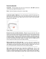
Move oil cooler to service position. 

Remove end cap (A) from left side of 

cooler. Slide screen (B) out from front of oil cooler. Unfasten knobs  (C) located 
on top of oil cooler, and remove plastic shield (F) from front of oil cooler. Release 
prop rod (D) at bottom of cooler and position hydraulic line to the front of it, so 
hose can move freely. Swing cooler up and away from radiator as shown (E). 
Insert prop rod into hole in frame to hold oil cooler in its service position. Remove 
floor shield (G) from tractor. 


Figure One 
——————————————————————————————————


Remove fuel tank. 

Remove four 5/16” screws and corresponding hardware (H), 

holding left front fender to frame. Remove fender. Disconnect wires from fuel 
sender (J), close fuel tank shut-offs, and disconnect fuel lines from bottom of 
tank. Remove two 1/2” carriage bolts and corresponding hardware (L) securing 

Содержание HR-9016 Turbo

Страница 1: ...1...

Страница 2: ...2...

Страница 3: ...4 Safety Precautions 5 Parts Photos 6 Standard Parts List 7 Standard Bolts List 7 Optional Heater Parts List 8 Electrical Connectors List 8 Optional Heater Installation 21 Decals Page 22 Hardware Tigh...

Страница 4: ...rences to right and left forward or rearward are from the operator s seat facing the steering wheel Safety Precautions All products are designed to give safe dependable service if they are operated an...

Страница 5: ...or serious injury CAUTION Indicates a potentially hazardous situation which if not avoided may result in minor or moderate injury IMPORTANT Indicates that the cab or property damage could result if in...

Страница 6: ...5 50 w jumper wire installed One Seat Belt Assembly C6180AS One 1 4 Yellow Loop One 1 2 Yellow Loop 30 3 4 X 3 4 NDAX 32 1 X 1 NDAX 36 1 2 X 3 4 NDAX STANDARD BOLTS LIST QUANTITY SIZE and ITEM Two 5 8...

Страница 7: ...m Carriage Bolt YD One M10 X 90 X 1 5mm Flange Bolt YD Two M10 X 1 5 Flange Nuts YD Two 3 8 X 1 1 2 Flange Bolt YD Two 3 8 Flange Nut YD One 31 64 X 52 3 8 V Belt One 1 2 X 24 1 2 V Belt One Compresso...

Страница 8: ...all fasteners and parts for reassembly Move oil cooler to service position Remove end cap A from left side of cooler Slide screen B out from front of oil cooler Unfasten knobs C located on top of oil...

Страница 9: ...ove four 3 8 screws and corresponding hardware R holding seat pan to frame Disconnect wire harnesses from seat Remove seat and seat pan assembly from tractor Figure Three Loosen hydraulic tank Remove...

Страница 10: ...rear tank mounts to cross frame If the tractor does not have a two post ROPS installed then remove and discard spacer plates AA If the tractor does have a two post ROPS installed then remove it using...

Страница 11: ...4 X 3 4 NDAX remove backing and place it along the seat mount starting where the 1 X 1 NDAX ended and working your way up to the platform mount 4 See Figure 7 Repeat for right side Figure Six Figure S...

Страница 12: ...Install hydraulic tank Slide hydraulic tank back into position Tighten front 1 2 carriage bolt and hardware X Install and tighten rear 1 2 hardware V Lift rear tank mount into position and secure to r...

Страница 13: ...e bracket Mark the hole locations on the side lips of the foot platform and remove the front bracket Drill two 9 16 holes through the lip of the foot platform at the marked locations Loosely bolt the...

Страница 14: ...nk and fender wall Lift rear tank mount into position and secure to left rear mounting bracket and crossframe with 3 4 hardware Torque nuts to 200 240 ft lbs Install 5 16 hardware M securing fender wa...

Страница 15: ...brass washers Remove the front right side window by opening window latch to half open position and pulling the latch down so that the stud passes through the slot in top surface of the latch Open the...

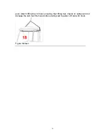
Страница 16: ...16 post Attach lifting bar to hoist ensuring that lifting bar chains or cables will not damage the cab roof Remove bolts securing cab to pallet Lift cab with hoist Figure Sixteen...

Страница 17: ...ce of the mounting brackets and the nut If it is not installed the nut could be pulled through the mounting bracket during a rollover and protection would be lost Torque nut to compress isolator until...

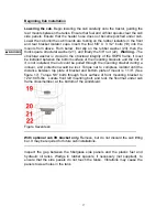
Страница 18: ...does not interfere with any moving parts of the engine Figure Twenty one Take the loose end of the jumper wire and attach it to the machine power source 36 Take the cab power wire and the breaker and...

Страница 19: ...Install heat shield to hydraulic tank with three 5 16 screws lockwashers and washers N Figure Twenty five Figure Three Finishing tractor reassembly Cut out shaded areas of machine floor shield as show...

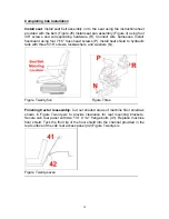
Страница 20: ...igure One Finishing cab installation Fit pre cut foot platform floor mat 43 onto foot platform and seat platform floor mats to seat platform If necessary trim floor mats to provide close fit to tanks...

Страница 21: ...the fastening hardware from the factory pedal Take the pedal off the unit and remove the rubber pads Take the rubber pads and attach them to the new hydraulic pedal 48 Attach the new pedal to the unit...

Страница 22: ...ting location where the alternator was originally located Use new provided belt tensioner to mount to factory location and onto compressor Re installing alternator Take alternator and original tension...

Страница 23: ...or clutch Connect the wires Re connect battery ground Please Note ALL A C charging MUST be performed by a certified A C technician as required by local provincial state federal regulations Filling coo...

Страница 24: ...on fitting Locate the water pump on right side of engine Remove the plug and screw in 3 8NPT X 5 8 barb 135 fitting This is the suction fitting Connecting heater hoses Locate the pressure heater hose...

Страница 25: ...eck for leaks and add anti freeze if required For maximum heater efficiency all air trapped in the heater system must be evacuated TIP To purge system of air open radiator cap while running the engine...

Страница 26: ...e 8 Gold Plated Hardware and Locknuts 1 4 157 18 5 16 324 37 3 8 48 65 7 16 77 104 1 2 117 159 9 16 169 2290 5 8 233 316 3 4 413 560 7 8 667 904 Size Grade 8 Metric Hardware and Locknuts M10 58 79 M12...

Страница 27: ......

Страница 28: ......

Страница 29: ......

Страница 30: ......

Страница 31: ......

Отзывы: