background image

43

> Change from previous revision

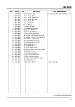
HR-4600

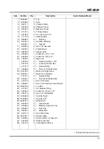
Item

Part No.

Qty.

Description

Serial Numbers/Notes

1

3006981

2

Tire

2

1003638

2

Rim

3

360111

2

Inflation Valve

4

361648

6

Washer, Thrust

5

361647

2

Bearing, Thrust

6

471214

2

Fitting, Grease

7

461393

2

Pin, Spring 1/4 x 2”

8

117139

1

Steering Axle

9

363562

4

Bushing

10

340491

1

Cylinder, Steering

557621

1

Seal Kit

11

443840

2

Nut, 1-12 Hex Jam

12

452022

1

Flat Washer, 1

13

366789

1

Spacer, Axle

14

460064

1

Cotter Pin, 1/4 x 1-1/2”

15

460026

4

Cotter Pin, 1/8 x 3/4”

16

153234

2

Ball Joint

400194

2

Screw, 5/16-18 x 1-3/4”

444718

2

Locknut, 5/16-18 Hex

471214

2

Grease Fitting

17

445666

2

Nut, 1/2-20 Slotted Hex

18

1002032

1

Ball Joint, Right Hand

19

1002031

1

Ball Joint, Left Hand

471214

2

Grease Fitting

20

445647

2

Nut, 3/8-24 Slotted Hex

21

443120

1

Nut, 1/2-20 Hex

22

445664

1

Nut, 1/2-20 Hex Left Hand Thread

23

3009378

1

Tie Rod

24

471227

1

45° Grease Fitting

25

460050

2

Cotter Pin, 3/16 x 1-1/4”

26

445710

2

Nut, 1-14 Slotted Hex

27

1004855

1

Spindle, Right

28

1004856

1

Spindle, Left

29

5002910

2

Wheel Hub

30

554329

2

Seal, Grease

31

500596

2

Bearing, Cup and Cone

32

545692

2

Dust Cap

33

354807

8

Wheel Nut

34

443110

4

Nut, 3/8-16 Hex

35

3010781

3

Weight, Rear

36

400284

4

Screw, 3/8-16 x 5” Hex Hd

37

452008

8

Washer, 3/8 Flat

38

446142

4

Lockwasher, 3/8 Hvy

Содержание HR 4600 Turbo 67862

Страница 1: ...rsonnel d entretien doivent être formés et conscients des dangers encourus Ils doivent lire avec attention le manuel avant d essayer de monter d utiliser de régler ou maintenir la machine Parts and Maintenance Manual Nomenclature Des Pieces De Rechange Manuel De Maintenance Onderhouds En Onderdelenhandleiding Wartungsanleitung Und Stückliste Reservedels og Vedlighold elseshåndbog HR 4600 Turbo TM ...

Страница 2: ... 2003 Ransomes Jacobsen Limited All Rights Reserved ...

Страница 3: ......

Страница 4: ... Manual to service the machine The Safety and Operation Manual must be kept in the pouch on the back of the seat at all times for reference by the operator Table of Contents Safety 1 1 Operating Safety 4 1 2 Important Safety Notes 5 SpecificationS 2 1 Product Identification 6 2 2 Engine 6 2 3 Tractor 6 2 4 Weights and Dimensions 7 2 5 Cutting Units 7 2 6 Accessories 7 2 7 Support Literature 7 Adju...

Страница 5: ... Description Serial Numbers Notes 1 123456 1 Mount Valve Indicates a piece part 2 789012 1 Valve Lift Includes Items 2 and 3 3 345678 1 Handle Serviced part included with Item 2 4 N S 1 Seal Kit Non serviced part included with Item 2 5 901234 6 1 Screw 1 4 20 x 2 Hex Head Indicates a part painted Jacobsen Orange Service Parts Paint Codes A paint code suffix is required when ordering painted parts ...

Страница 6: ...not in perfect working order or is without decals guards shields discharge deflectors or other protective devices securely fastened in place 9 Never disconnect or bypass any switch 10 Carbon monoxide in the exhaust fumes can be fatal when inhaled Never operate the engine without proper ventilation 11 Fuel is highly flammable handle with care 12 Keep the engine clean Allow the engine to cool before...

Страница 7: ...Authorized Textron Turf Care and Specialty Products Dealer who is kept informed of the latest methods to service this equipment and can provide prompt and efficient service Use of other than original or authorized Textron Turf Care and Spedialty Products parts and Accessories will void the warranty WARNING The operator back up system on this tractor prevents the tractor from starting unless the br...

Страница 8: ...0 rpm Low Idle 1200 rpm Lubrication Capacity 5 5 U S qts 5 2 liter Type SAE 10W30 API Classification CD CE Air Filter Donaldson dry type with evacuator valve and service indicator Alternator 40 Amp 2 3 TRACTOR ________________________________________________________________ Tires Front 26 x 12 12 6 ply Rear 20 x 10 8 4 ply Pressure 10 12 psi 69 83 kPa Battery Type 12V 600 Cold Cranking Amps Group ...

Страница 9: ...Pa 2 6 ACCESSORIES____________________________________________________________ Contact your area Textron Turf Care and Specialty Products dealer for a complete listing of accessories and attachments TRACTOR Air Blow Gun JAC5098 Orange Touch up Paint 12 oz spray 554598 2 Post ROPS with Seat Belt 67844 All Weather Cab 67845 Canopy Sunshade 67857 Standard Seat Suspension 66170 Deluxe Seat Suspension ...

Страница 10: ...n to increase speed Tighten nut to hold adjustment in place Figure 3A 3 3 BELT____________________________________________________________________ Inspect and adjust new belt after first ten hours of operation Adjust every 100 hours thereafter Adjust alternator pulley so belt deflects 1 4 to 5 16 6 8 mm with a 20 lb push at midpoint between pulleys See engine manual If tension is incorrect loosen ...

Страница 11: ...justment is preset at the factory on all new tractors and replacement pumps Further adjustment is not required unless the pump has been disassembled for repair or service To adjust neutral 1 Disconnect traction pedal linkage from pump 2 Place tractor securely on jack stands so All wheels are raised off ground 3 Check that tow valve H is closed 4 Engage parking brake and set mow switch to neutral M...

Страница 12: ...reverse travel stop bolt L Slide bolt forward in slotted hole to increase speed back to reduce speed Tighten nut to hold adjustment in place 4 Start engine and check speed Repeat procedure until 5 6 mph 8 9 kph reverse speed is attained Figure 3E 3 7 REEL LIMIT SWITCH _______________________________________________________ The left and right wing lift arms are equipped with proximity switches whic...

Страница 13: ...eck refer to Figure 3H Raise wing decks approximately 12 and support underneath with blocks Lower deck so it is completely resting on blocks 4 Remove pin from rear gauge wheel yoke and reposition in bracket for desired height of cut Figure 3G Figure 3H Tire pressure Check air pressure in caster tires while tires are cool Maintain air pressure between 20 25 psi 138 173 kPa to improve accuracy of cu...

Страница 14: ...rod M 3 Turn tie rod M to provide proper tow in Tow in must not exceed 1 16 1 5 mm K Retighten jam nuts 4 After adjusting tie rod adjust steering cylinder by threading the rod N in or out of ball joint so spindle arm L clears the stop on the axle by 1 32 to 3 32in 0 8 to 2 mm O when cylinder is fully extended Figure 3I 1 32 3 32 0 8 2 mm J M N O K K 0 to1 16 L 0 to 1 5 mm LF016 ...

Страница 15: ...gine During the break in period Textron Turf Care and Spedialty Products recommends the following 1 During the first 50 hours of operation a new engine should be allowed to reach an operating temperature of at least 140 F 60 C prior to operation at full load 2 Check the engine oil level twice daily during the first 50 hours of operation Higher than normal oil consumption is not uncommon during the...

Страница 16: ...ck Use clean fresh 2 Diesel fuel Minimum Cetane Rating 45 Refer to Engine Manual for additional information Check fuel lines and clamps every 50 hours Replace fuel lines and clamps at the first sign of damage Store fuel according to local state or federal ordinances and recommendations from your fuel supplier Never overfill or allow the tank to become empty 4 6 FUEL SYSTEM ________________________...

Страница 17: ...onnect the BLACK jumper cable from the negative terminal on the good battery to the frame of tractor with discharged battery After cables have been connected start the engine on the vehicle with the good battery then start the tractor 4 9 CHARGING BATTERY _____________________________________________________ 1 Refer to Section 4 7 Read the Battery and Charger s manual for specific instructions 2 W...

Страница 18: ... Kinked or twisted hoses can restrict the oil flow causing the system to malfunction and the oil to overheat and also lead to hose failure 4 11 HYDRAULIC OIL __________________________________________________________ Refer to Section 6 2 for specific maintenance intervals Drain and replace the hydraulic oil after a major component failure or if you notice the presence of water or foam in the oil o...

Страница 19: ...ow 1 Make certain all terminals and connections are clean and properly secured 2 Check the operator backup system fuses and circuit breakers regularly If the operator backup does not function properly and the problem cannot be corrected contact an authorized Textron Turf Care and Spedialty Products dealer 3 Keep the wire harness and all individual wires away from moving parts to prevent damage 4 M...

Страница 20: ...ean Use compressed air 30 psi maximum to clean the fins To clean radiator 1 Turn out thumb screws A securing hydraulic oil cooler to the radiator and tip cooler away from radiator as shown 2 Use a blow gun to clean the radiator and oil cooler fins Note A sliding panel located under the frame can be loosened and pulled back to allow dirt and debris to fall though frame 3 Fasten oil cooler to radiat...

Страница 21: ... hours or once a month Use an accurate low pressure tire gauge 3 Keep tires inflated to 10 12 psi 69 87 kPa 4 18 WHEEL MOUNTING PROCEDURE ____________________________________________ 1 Remove dirt grease and oil from stud thread Do not lubricate threads 2 Position wheel on hub and inspect to insure full contact between mounting surface of wheel and hub or brake drum 3 Finger tighten all hardware t...

Страница 22: ...ully examine the blades to make sure they are in good operating condition Blades showing any bends G grooves H or cracks J must be replaced 2 Any of the above conditions can cause a piece of the blade to break away and be hurled from the mower causing very serious injury to bystanders or property damage 3 A bent blade could have a microscopic crack G that can grow and allow a piece of the blade to...

Страница 23: ... blade after sharpening 5 Attach blade to mower Install blades so cutting edges C face the direction of rotation as shown in Figure 4G Beveled cutting edge of blade must face in toward deck housing IMPORTANT The two right hand blades D must be installed on the right wing deck using left hand threaded hardware The remaining left hand blades E are mounted on the left wing and the center deck using r...

Страница 24: ...gine is warm remove drain plug drain the oil from the crankcase and change oil filter Install drain plug and refill with fresh oil Torque drain plug to 22 ft lb 30 Nm 2 Clean exterior of engine Paint exposed metal or apply a light coat of rust preventative oil 3 Add a fuel conditioner or biocide to prevent gelling or bacterial growth in fuel See your local fuel supplier Cutting Units 1 Wash the cu...

Страница 25: ...Change fuel filter Bleed fuel lines 4 5 4 6 2 Air cleaner dirty 2 Inspect and replace air filter 4 4 3 Injectors fuel pump 3 Consult engine manual 4 Engine problem 4 Consult engine manual Engine stops 1 Fuel tank empty 1 Fill with fresh fuel and bleed fuel lines 4 5 4 6 2 Interlocks not set before leaving operator s seat 2 Engage parking brake and set mow switch to OFF Engine overheating 1 Coolant...

Страница 26: ...ed on the instrument panel The traction pedal lift limit and brakes are controlled by small proximity switches mounted on the frame of the tractor If an input lamp does not light an inactive condition is indicated This could be caused by a fuse faulty switch a switch that needs adjustment or poor connection The electrical connections to the solenoids on the hydraulic valves are also equipped with ...

Страница 27: ... NLGI Grade 2 Service Class GB II Manual grease gun with NLGI Grade 2 Service Class LB III Engine Oil See Section 4 3 IV Textron Turf Care and Spedialty Products Hydraulic Oil SAE 10W30 WARNING Before you clean adjust or repair this equipment disengage all drives lower implements to the ground engage parking brake stop engine and remove key from ignition switch to prevent injuries Recommended Serv...

Страница 28: ...inders 6 Fittings 4 Caster Wheel Spindles 8 Fittings 5 Brake Pedal Pivot 2 Fittings 6 Traction Pedal Pivot 1 Fitting 7 Ball Joint 2 Fittings 8 Steering Pivot 2 Fittings 9 Steering Cylinder 2 Fittings 10 Axle Pivot 1 Fitting 11 Caster Wheel Axle 12 Fittings F2 100 Hours 12 U joint Driveshaft 3 Fittings 1 12 12 5 6 7 7 8 8 9 10 9 LF023 1 1 1 1 1 2 2 2 3 3 3 3 3 3 4 4 4 4 4 4 4 4 11 11 11 11 11 11 11...

Страница 29: ...lics 61 20 1 Charge Pressure and Steering Hydraulics 62 21 1 Gear Pump Hydraulics 63 22 1 Return Hydraulics 64 23 1 Lift Valve and Filter Mounting 65 24 1 Lift Hydraulics 66 25 1 Hydraulic Clamps 68 26 1 Front Wheel Motor and Deck Motor Drains 69 27 1 Wing Deck Control Valves 70 28 1 Center Deck Control Valve 71 29 1 Wing Deck Hydraulics 72 30 1 Center Deck 73 31 1 Wire Harness and Controller Box ...

Страница 30: ...d utilisation pour ce qui concerne l entretien de la machine Le Manuel de Sécurité et la Notice d utilisation doivent toujours rester dans la pochette situé derrière le siège Table des Matières SECURITE 1 1 CONSIGNES DE SECURITE RELATIVES AU FONCTIONNEMENT 4 1 2 CONSIGNES DE SECURITE IMPORTANTES 5 SPECIFICATIONS 2 1 DESCRIPTION 6 2 2 MOTEUR 6 2 3 TRACTEUR 6 2 4 POIDS DIMENSIONS 7 2 5 UNITES DE COU...

Страница 31: ... 3 345678 1 Poignée Pièce de rechange comprise dans l article 2 4 N S 1 Kit de joints Pièce non réparable comprise dans l article 2 5 901234 6 1 Vis Tête Hex 1 4 20 x 2 Indique une pièce peinte en orange Jacobsen Pièces de Rechange Codes Peinture Il faut un suffixe pour passer commande de pièces peintes Les codes couleur des peintures figurent dans la Nomenclature des Pièces de Rechange et se prés...

Страница 32: ...vous servez jamais d une machine qui ne dispositifs de protection déflecteurs de déversement ou tout autre dispositif de sécurité manquent sont mal positionnés ou desserrés 9 Ne débranchez et ne passez jamais outre les interrupteurs 10 L inhalation d oxyde de carbone des fumées d échappement peut s avèrer mortelle Le moteur ne doit jamais tourner sans brassage adéquat 11 Maniez prudemment le carbu...

Страница 33: ...us renseignements complémentaires ou services d entretien supplémentaires car il est au courant des toutes dernières techniques et répondra rapidement à vos demandes La garantie est annulée en cas d utilisation de pièces ou accessoires autres que ceux de Textron Turf Care and Specialty Products AVERTISSEMENT Le système de secours de la machine l empêche de démarrer quand la pédale de frein n est p...

Страница 34: ...min A vide Ralenti 1 200 tr min Graissage Volume 5 2 litres Type SAE 10W30 Catégorie API CD CE Filtre à air Donaldson type sec avec soupape d évacuation et indicateur de service Alternateur 40 A 2 3 TRACTEUR_______________________________________________________________ Pneus Avant 26 x 12 12 6 nappes Arrière 20 x 10 8 4 nappes Pression 69 83 kPa Batterie Type 12 V 600 A Démarrage à froid Groupe B...

Страница 35: ...concessionnaire agréé de Textron Turf Care Specialty Products pour obtenir la liste des accessoires et accouplements TRACTEUR Pistolet de ventilation forcée JAC5098 Peinture de retouche orange 340 g 554598 Protection au retournement 2 arceaux avec ceinture de sécurité 67844 Cabine de pilotage toutes saisons 67845 Auvent verrière 67857 Suspension de siège standard 66170 Suspension de siège de luxe ...

Страница 36: ...éduire la vitesse ou vers le bas pour l augmenter Serrez l écrou pour maintenir le réglage Schéma 3A 3 3 COURROIE_______________________________________________________________ Vérifiez et réglez la nouvelle courroie après les dix premières heures de fonctionnement ensuite toutes les 100 heures Réglez la poulie d alternateur pour obtenir une déflexion de courroie de 6 8 mm en appliquant une force ...

Страница 37: ...res ne sont pas requis sauf s il faut déposer la pompe pour la réparer ou l entretenir Réglages des points morts 1 Débranchez la tringlerie de la pédale de traction la reli ant à la pompe 2 Placez la machine sur crics afin que toutes les roues soient levées 3 Veillez à ce que la soupape de remorquage H soit fermée 4 Serrez le frein de stationnement et placez l interrupteur de tonte au point mort V...

Страница 38: ...ction se trouve au point mort vérifiez la position de l interrupteur correspondant I Réglez l interrupteur vers le bas ou le haut de façon à ce que la flèche M soit centrée dessus Dès obtention du réglage correct le voyant 5 du contrôleur s allume quand la clé de contact est en position de démarrage 5 Faites démarrer le moteur et vérifiez la vitesse Répétez ceci jusqu à obtention d une vitesse de ...

Страница 39: ...sur ROULER pour actionner le contrôleur Ne démarrez pas le moteur 4 Levez la biellette de levage à une hauteur de 250 mm puis maintenez la avec une cale 5 Quand la biellette de levage est maintenue desserrez le composant P et faites monter ou descendre la bride de l interrupteur Q jusqu à ce que le voyant correspondant du contrôleur s éteigne 16 à gauche et 19 à droite Serrez le composant P 6 Suiv...

Страница 40: ...s sur la partie supérieure de l axe Repositionnez s il y a lieu l ensemble de la roue dans les orifices indiquant la hauteur de coupe 3 Reportez vous au schéma 3H pour le réglage des roues de référence arrière Levez les châssis latéraux à 30 cm et maintenez les à l aide de cales Abaissez les châssis de façon à ce qu ils reposent entièrement sur les cales 4 Déposez la goupille de la chape de la rou...

Страница 41: ...uplement M pour obtenir un alignement correct qui ne doit pas dépasser 1 5 mm K puis resserrez les contre écrous 4 Après avoir réglé la barre d accouplement réglez le vérin de direction en filetant la tige N vers l intérieur ou l extérieur de la rodule de façon à ce que le bras pivotant L laisse entre 0 8 et 2 mm O de libre sur la butée de l essieu quand le vérin est sorti complètement Schéma 3I 0...

Страница 42: ...ant pour prolonger au maximum sa vie utile Adressez vous au fabricant du moteur pour recevoir des copies supplémentaires du manuel Le rodage correct d un nouveau moteur contribue à améliorer considérablement sa performance et prolonger sa vie utile Lors du rodage Textron Turf Care and Specialty Products recommandent ce qui suit 1 Pendant les 50 premières heures de fonctionnement un nouveau moteur ...

Страница 43: ...on de poussières et de diverses impuretés dans le moteur Quand un service d entretien est nécessaire nettoyez tout d abord l extérieur du boîtier du filtre avant de retirer aussi prudemment que possible l ancien élément et le jeter 1 Nettoyez prudemment l intérieur du boîtier du filtre sans laisser la poussière s infiltrer dans l entrée d air 2 Examinez le nouvel élément N utilisez pas d élément e...

Страница 44: ...nuel du Moteur 4 7 BATTERIE________________________________________________________________ La clé de contact doit être sur Arrêt avant d être retirée et de procéder à tout service d entretien de la batterie Serrez bien les câbles aux bornes de la batterie et appliquez une fine couche de graisse de silicium diélectrique sur les bornes et extrémités des câbles pour éviter leur corrosion Veillez à c...

Страница 45: ...ême qu à la notice accompagnant la batterie et le chargeur pour tous renseignements complémentaires 2 Quand possible retirez la batterie de la machine avant de procéder à sa charge Si la batterie n est pas hermétique veillez à ce que l électrolyte recouvre les plaquettes de toutes les cellules 3 Veillez à ce que le chargeur soit sur Arrêt avant de le brancher aux bornes de la batterie comme spécif...

Страница 46: ...ouplements et provoquer des fuites d huile e Les flexibles tordus limitent le débit d huile et empêchent le circuit de fonctionner normalement l huile surchauffe et les flexibles deviennent éventu ellement défectueux 4 11 HUILE HYDRAULIQUE______________________________________________________ Reportez vous au chapitre 6 2 pour tous renseignements concernant les intervalles de maintenance Vidangez ...

Страница 47: ... deux filtres dès que le voyant s allume Remarque Le voyant risque de s allumer lorsqu il fait froid et de rester ainsi tant que l huile n atteint pas sa température de service Attendez que l huile se réchauffe et que le voyant s éteigne avant d utiliser la machine Remplacement des filtres à huile hydraulique 1 Déposez les anciens filtres 2 Posez les nouveaux filtres et serrez les uniquement à la ...

Страница 48: ... principal 5 Vérifiez la batterie et son circuit de charge 6 Ne nettoyez pas les surfaces environnantes des raccordements et composants électriques Le contrôleur électronique C se trouvant derrière le siège de l opérateur supervise et contrôle le circuit électrique Il est muni de quatre rangées de DEL qui servent également au dépistage des défauts du circuit Voir le chapitre 5 2 Les circuits sont ...

Страница 49: ...i maxi Entretien du radiateur 1 Tournez les vis à molette A fixant le refroidisseur d huile hydraulique au radiateur et penchez le refroidis seur en l éloignant du radiateur tel que représenté sur le schéma 2 Utilisez un pistolet à air comprimé pour nettoyer le radiateur et les ailettes du refroidisseur d huile Remarque Il est possible de desserrer et de tirer en arrière le panneau glissant se tro...

Страница 50: ...toutes les 50 heures ou mensuellement Utilisez une jauge pour pneus de basse pression 3 Leur pression doit se situer entre 69 et 87 kPa 4 18 POSE DES ROUES ________________________________________________________ 1 Enlevez les saletés la graisse et l huile des filets des goujons et ne graissez pas les filets 2 Placez la roue sur son moyeu en veillant à ce que sa surface de montage soit totalement ...

Страница 51: ...tés de coupe sont déposées de la machine Veillez toujours à ce qu elles fonctionnent cor rectement Remplacez les lames déformées G rayées H ou fissurées J 2 Il est toujours possible qu un morceau de lame se casse et soit projeté de la machine et risque de blesser gravement les personnes environnantes ou d endommager les biens 3 Une lame déformée peut en fait avoir une fissure microscopique G pouva...

Страница 52: ...5 Fixez la lame à l unité de coupe Placez les lames de façon à ce que leurs bords tranchants C fassent face au sens de rotation Schéma 4G Les bords tranchants biseautés des lames doivent se trouver en face du logement de châssis IMPORTANT Les deux lames de droite D doivent être posées sur le châssis latéral droit à l aide des composants de gauche Les lames restantes de gauche E se posent sur l ail...

Страница 53: ...core chaud déposez le bouchon de vidange vidangez l huile du vilebrequin et remplacez le filtre à huile Couplez le bouchon de vidange à 30 Nm 2 Nettoyez l extérieur du moteur Peignez les surfaces extérieures ou appliquez une fine couche d anti corrosif 3 Ajoutez un conditionneur de carburant ou biocide pour éviter la gélification ou le développement de bactéries dans le carburant Adressez vous à v...

Страница 54: ...ltre carburant et purger les conduites carburant 4 5 4 6 2 L épurateur d air est sale 2 Vérifier et remplacer le filtre à air 4 4 3 Les injecteurs pompe carburant 3 Voir le Manuel du Moteur 4 Problème de moteur 4 Voir le Manuel du Moteur Arrêt du moteur 1 Le réservoir carburant est vide 1 Remplir de carburant neuf et purger les conduites car burant 4 5 4 6 2 Interverrouillage non réglé avant l aba...

Страница 55: ... ENTREES SORTIES Voyant Circuit Voyant Circuit 3 Programme lancé contrôleur sous tension 31 Relais indicateur de préchauffage Bougie allumée 4 Clé de contact sur Démarrer 32 Essai de voyants 5 Interrupteur de démarrage au point mort Pédale de traction au point mort 33 Relais de démarrage et indicateur 6 Interrupteur de frein Frein serré 34 Bobine de pause de soupape carburant 7 Interrupteur de siè...

Страница 56: ...uis et en cherchant une sortie correspondante Notez que tous les interrupteurs ne se trouvent pas sur le pupitre des instruments La pédale de traction l interrupteur de fin de course des rouleaux et les freins sont contrôlés par de petits relais montés sur le châssis de la machine Quand un voyant d entrée ne s allume pas il s agit d un état inactif pouvant résulter d un fusible interrupteur défect...

Страница 57: ...le commence à ressortir N utilisez pas de pistolets à l air comprimé 3 Appliquez plusieurs gouttes d huile SAE 30 toutes les 50 heures ou quand il s en avère nécessaire sur tous les leviers pivots et points de friction non mentionnés dans le tableau de graissage pour qu ils fonction nement plus facilement 4 Déposez les roues et entretenez les roulements une fois par an AVERTISSEMENT Avant de netto...

Страница 58: ...gramme de graissage et de maintenance Toutes les 8 10 heures Toutes les 50 heures Toutes les 100 heures Toutes les 250 heures Toutes les 400 heures Toutes les 500 heures Toutes les 1 000 heures Par an Voir chap Type de graisse Filtre à air AR R 4 4 Charge de batterie I 4 9 Courroie I A I A R 3 3 Frein I A A 3 4 Circuit de refroidissement I C A R 4 15 Huile moteur I R R 4 2 III Filtre à huile moteu...

Страница 59: ...LEVAGE 6 RACCORDS 4 PIVOTS DE ROUE STABILISATRICE 8 RACCORDS 5 PIVOT DE PÉDALE DE FREIN 2 RACCORDS 6 PIVOT DE PÉDALE DE TRACTION 1 RACCORD 7 ROTULE 2 RACCORDS 8 PIVOT DE DIRECTION 2 RACCORDS 9 VÉRIN DE DIRECTION 2 RACCORDS 10 PIVOT D ESSIEU 1 RACCORD 11 ESSIEU DE ROUE STABILISATRICE 12 RACCORDS F2 100 HEURES 12 ARBRE DE COMMANDE EN U 3 RACCORDS 1 12 12 5 6 7 7 8 8 9 10 9 LF023 1 1 1 1 1 2 2 2 3 3 ...

Страница 60: ...riften in de Veilig heid Bedieningshandleiding wanneer de machine een service of onderhoudsbeurt krijgt De Veiligheids Bedieningshandleiding moet voor raadpleging door de bestuurder altijd te vinden zijn in het opbergvak achter de zitting Inhoudsopgave VEILIGHEID 1 1 OPERATIONELE VEILIGHEID 4 1 2 BELANGRIJKE VEILIGHEIDSOVERWEGINGEN 5 SPECIFICATIES 2 1 PRODUCTIDENTIFICATIE 6 2 2 MOTOR 6 2 3 TRACTOR...

Страница 61: ... Item Stuknr Hoev Omschrijving Serienummers Opmerkingen 1 123456 1 Montage klep Duidt op samenstellend deel 2 789012 1 Klep heffing Imvat items 2 en 3 3 345678 1 Handgreep Serviced onderdeel opgenomen in item 2 4 N S 1 Afdichtingskit Non serviced onderdeel opgenomen in item 2 5 901234 1 Schroef 1 4 20x2 zeskant Duidt op Jacobsen oranje gelakt onderdeel Service onderdelen Lakcodes Er is een lakcode...

Страница 62: ...edrijf sstaat verkeert geen decalplaatjes heeft of waarvan de beschermkappen keerschotten en of andere beveilig ingsinrichtingen niet of onvoldoende stevig zijn bevestigd 9 Geen enkele schakelaar mag ooit worden onderbroken of geshunt 10 Koolmonoxide in de uitlaatgassen kan bij inademing dodelijk zijn Bedien de motor nooit zonder afdoende ventilatie 11 Brandstof is in hoge mate ontvlambaar en dien...

Страница 63: ...ler Onze dealers worden op de hoogte gehouden van de nieuwste onderhoudsmethoden ten behoeve van deze machines en kunnen een snelle en efficiënte service verlenen Gebruik van andere dan originele en goedgekeurde Textron Turf Care Specialty Products onderdelen en accessoires maakt deze garantie ongeldig WAARSCHUWING Het operationele back up systeem van deze tractor voorkomt het starten ervan tenzij...

Страница 64: ...ring Inhoud 5 2 liter Type SAE 10W30 API classificatie CD CE Luchtfilter Donaldson droog type met vacuümklep en service indicator Wisselstroomdynamo 40 Amp 2 3 TRACTOR ________________________________________________________________ Banden Voor 26x12 12 6 koordlagen Achter 20x10 8 4 koordlagen Spanning 69 83 kPa Accu Type 12 V 600 Amp koudaanslingervermogen Groep BCI 24 Remmen Bedrijfsrem dynamisc...

Страница 65: ...m contact op met de Textron Turf Care Specialty Products Dealer in uw gebied voor een compleet overzicht van accessoires en aanzetstukken TRACTOR Luchtblaaspistool JAC5098 Oranje reparatielak 340 g spray 554598 ROPS met 2 stijlen en veiligheidsriem 67844 Weerbestendige cabine 67845 Overkapping Zonnescherm 67857 Standaard stoelvering 66170 Deluxe stoelvering 66171 Eendelige stoel met hoge rug 66172...

Страница 66: ...elheid Draai de moer weer vast om de nieuwe positie te handhaven Afb 3A 3 3 RIEM ____________________________________________________________________ Een nieuwe riem moet na de eerste tien bedrijfsuren worden geïnspecteerd en bijgesteld Vervolgens na iedere 100 bedrijfsuren Regel de poelie van de wisselstroomdynamo zodanig dat de riem onder een druk van 88 8 Nm halverwege tussen de poelies 6 8 mm ...

Страница 67: ...n fabriekinstelling die geldt voor alle nieuwe tractors en vervangingspompen Verdere bijstelling is overbodig tenzij de pomp is gedemonteerd voor reparatie of onderhoud Neutraalafstelling 1 Ontkoppel de tractiepedaalverbinding van de pomp 2 Zet de tractor stevig op krikken waarbij alle wielen vrij van de grond moet komen 3 Controleer of de sleepklep H is gesloten 4 Trek de parkeerrem aan en zet de...

Страница 68: ...e positie van de neutraalschakelaar I te worden gecontroleerd Verzet de schakelaar omhoog of omlaag zodat de wijzer M op de tractiepedaalbeugel zich er gecentreerd boven bevindt Wanneer correct is bijgesteld moet waarschuwingslampje 5 op de controller gaan branden wanneer de contactschakelaar in de AAN stand wordt gezet 5 Start de motor en controleer de snelheid Herhaal de procedure eventueel totd...

Страница 69: ...ntactsleutel in de AAN stand om de controller te activeren maar start de motor niet 4 Breng de ene hefarm met de hand ongeveer 250 mm omhoog en laat hem op een steunblok rusten 5 Zet vervolgens de bevestiging P los en verstel de schakelaarbeugel Q op of neer totdat het correspon derende lampje op de controller uitgaat 16 ingeval van links 19 ingeval van rechts Zet de bevestiging P weer vast 6 Herh...

Страница 70: ...n Verzamel extra afstandsstukken bovenaan de as Herpositioneer de wielmontage in de gaten aangegeven voor de maaihoogte 3 Zie Afb 3H voor afstelling van de achterste spoorwielen op het voordek Breng de zijdekken ongeveer 30 cm omhoog en zet ze op steunblokken ervoor zorgend dat ze hier volledig op rusten 4 Verwijder de pen uit het achterste spoorwieljuk en herpositioneer hem in de beugel ten behoe...

Страница 71: ...i aan de spoorstang M om de juiste sporing te bereiken die niet meer dan 1 5 mm mag zijn K Draai de contramoeren weer vast 4 Na regeling van de spoorstang dient de stuurcilinder te worden afgesteld door stang N zover in of uit het kogelscharnier te draaien dat de spilarm L 0 8 2 mm van de begrenzer op de as blijft O wanneer de cilinder geheel is uitgeschoven Afb 3I 0 8 2 mm J M N O K K 0 1 5 mm L ...

Страница 72: ...rikant verzekeren u van een maximale levensduur van de motor Voor het bestellen van een vervangende motorhandleiding dient contact met de betreffende fabrikant te worden opgenomen Geef de motor de gelegenheid om goed in te lopen aangezien dit een aanzienlijk verschil maakt voor de prestatie en gebruiksduur ervan Textron Turf Care Specialty Products adviseert u om tijdens de inloopperiode het volge...

Страница 73: ...g Onnodige verwijdering van het filter verhoogt het risico op het toevoeren van stof en andere verontreinigingen naar de motor Wanneer service is vereist reinig dan eerst de buitenkant van het filterhuis en verwijder daarna het oude element zo voorzichtig mogelijk 1 Maak de binnenkant van het filterhuis zorgvuldig schoon ervoor zorgend dat er geen stof in de luchtin laat komt 2 Inspecteer het nieu...

Страница 74: ...t het filterhuis worden schoongemaakt evenals het gedeelte rond het filter Voorkomen moet worden dat vuil het brandstofsysteem binnendringt Ontlucht het brandstofsysteem na verwijdering van het brandstoffilter en de leidingen of wanneer de brandstoftank is leeggeraakt Zie de Motorhandleiding Vervanging van het brandstoffilter 1 Sluit de brandstofklep op de tank Verwijder het oude fil ter en ontdoe...

Страница 75: ...bel vanaf de negatieve klem van de goede accu aan op het chassis van de tractor met de ontladen accu Na aansluiting van de kabels dient de motor van het voertuig met de goede accu te worden gestart gevolgd door het starten van de tractormotor 4 9 ACCULADING_____________________________________________________________ 1 Zie sectie 4 7 Lees de accu en acculaderhandleiding voor specifieke instructies...

Страница 76: ...oor het systeem storing gaat vertonen met als resultaat oververhitting van de olie terwijl de slang het kan begeven 4 11 HYDRAULIEKOLIE_________________________________________________________ Zie sectie 6 2 for specifieke perioden tussen onderhoudsbeurten Na het falen van een belangrijk onderdeel dient de hydrauliekolie te worden afgetapt en ververst Het laatste geldt ook als u de aanwezigheid va...

Страница 77: ...en beide filters zo spoedig mogelijk na het gaan branden van het lampje te worden vervangen N B Tijdens koud weer kan het waarschuwingslampje blijven branden totdat de olie op bedrijfstemperatuur is gekomen Wacht tot dit gebeurt en het lampje uitgaat alvorens de tractor te gaan bedienen Vervanging van hydraulische filters 1 Verwijder de oude filters 2 Installeer nieuwe filters en draai deze handva...

Страница 78: ...bedrading 5 Controleer de accu en het acculaadstroomcircuit 6 Rond elektrische aansluitingen en componenten mag niet worden gewassen noch een drukspuit worden gebruikt Het elektrisch systeem wordt gecontroleerd en bestuurd door de elektronische controller C achter de bestuurdersruimte De controller is uitgerust met vier LED banken die kunnen worden gebruikt voor foutopsporing in het elektrisch sys...

Страница 79: ...ebruik perslucht maximaal 30 psi om de ribben te reinigen Reiniging van de radiateur 1 Draai de duimschroeven A die de hydrauliekoliekoeler aan de radiateur bevestigen eruit en kantel de koeler van de radiateur weg zoals afgebeeld 2 Gebruik een blaaspistool om de radiateur en oliekoel erribben schoon te maken N B Een schuifpaneel onder het frame kan worden losgezet en teruggetrokken om vuil en afv...

Страница 80: ...een nauwkeurig werkende lagedrukmeter om de bandenspanning te meten 3 Handhaaf een bandenspanning van 69 87 kPa 4 18 WIELMONTAGEPROCEDURE________________________________________________ 1 Verwijder vuil gras en olie van de tapboutdraadgangen maar smeer ze niet 2 Plaats het wiel op de naaf en controleer of er volledig contact is tussen het montagevlak van het wiel en de naaf of remtrommel 3 Zet all...

Страница 81: ...ie verkeren Messen die verbuigingen G groeven H of scheurtjes J ver tonen moeten worden vervangen 2 Ieder van bovengenoemde gebreken kan ertoe leiden dat een stuk van het mes afbreekt en wordt weggeslingerd waardoor omstanders ernstig lichamelijk letsel kunnen oplopen en waarvan ook beschadiging van eigendommen het gevolg kan zijn 3 Een gebogen mes kan een microscopisch scheurtje G hebben dat grot...

Страница 82: ...chting ter controle van de symmetrie na het aanscherpen 5 Bevestig de messen weer aan de maaimachine en installeer ze zodanig dat de snijranden C in de rotatierichting wijzen zie Afb 4G De afgeschuinde snijrand wijst dus in de richting van het maaidekhuis BELANGRIJK De twee rechtermessen D moeten op het rechterdek worden gemonteerd met gebruikmaking van linksgangige bevestigingen De linkermessen E...

Страница 83: ...den verwijderd om de olie uit de krukkast af te voeren en het oliefilter te worden vervangen Plaats de aftapplug terug en vul de krukkast met verse olie Geef de aftap plug een draaikoppel van 30 Nm 2 Reinig het binnenste van de motor Lak blootgesteld metaal of breng een dunne laag roestwerende olie op 3 Voeg een brandstofconditioner of biocide toe om gelering van of bacteriegroei in de brandstof t...

Страница 84: ... brandstof Vervang het brandstoffilter Ontlucht de brandstofleidingen 4 5 4 6 2 Vuil luchtfilter 2 Inspecteer en vervang het luchtfilter 4 4 3 Injectors brandstofpomp 3 Raadpleeg de motorhandleiding 4 Motorprobleem 4 Raadpleeg de motorhandleiding Motor stopt 1 Brandstoftank leeg 1 Vullen met verse brandstof en brandstofleidingen ontluchten 4 5 4 6 2 Vergrendelsysteem niet geactiveerd vóór het verl...

Страница 85: ...de AAN stand moeten staan Inactieve lampjes 1 2 8 14 15 17 18 24 26 27 29 30 48 niet gebruikt Controllerfuncties per lampjesnummer Lampje aan circuit is actief Lampje uit circuit is inactief INPUTS OUTPUTS Lampje Circuit Lampje Circuit 3 Programma actief geeft aan dat controller voeding ontvangt 31 Gloeibougierelais indicator gloeibougie aan 4 Contactschakelaar in start positie 32 Lichttest 5 Neut...

Страница 86: ...angen en sprake is van een corresponderend uitgangssignaal Onthoud dat niet alle schakelaars zich op het instrumentenpaneel bevinden De tractiepedaal kooihefafslag en remmen worden bestuurd door kleine tongenschakelaars op het frame van de tractor Als een ingangslampje niet gaat branden wordt een inactieve staat aangegeven Dit kan worden veroorzaakt door een doorgeslagen smeltveiligheid een defect...

Страница 87: ...len 3 Ten behoeve van soepele werking van alle hefbomen draai en andere frictiepunten die niet op het smeerschema zijn afgebeeld dienen deze iedere 40 uur of wanneer vereist een paar druppels SAE 30 olie te krijgen 4 Eenmaal per jaar moeten de wielen er worden afgehaald om de lagers opnieuw te smeren WAARSCHUWING Alvorens te beginnen met schoonmaken afstellen of reparatie van deze machine dienen a...

Страница 88: ...10W30 Aanbevolen tussentijden voor service en smering Iedere 8 10 bed rifs uren Iedere 50 bed rifs uren Iedere 100 bed rifs uren Iedere 50 bed rifs uren Iedere 400 bed rifs uren Iedere 500 bed rifs uren Iedere 1000 bed rifs uren Jaar lijks Zie sectie Smeer type Luchtfilter AR R 4 4 Acculading I 4 9 Riem I A I A R 3 3 Remmen I A A 3 4 Koelsysteem I C A R 4 15 Motorolie R R 4 2 III Motoroliefilter R...

Страница 89: ...PUNTEN 4 ZWENKWIELSPINDELS 8 SMEERPUNTEN 5 REMPEDAALDRAAIPEN 2 SMEERPUNTEN 6 RACTIEPEDAALDRAAIPEN 1 SMEERPUNT 7 KOGELSCHARNIER 2 SMEERPUNTEN 8 STUURDRAAIPEN 2 SMEERPUNTEN 9 STUURCILINDER 2 SMEERPUNTEN 10 ASDRAAIPEN 1 SMEERPUNT 11 ZWENKWIELAS 12 SMEERPUNTEN F2 100 BEDRIJFSUREN 12 U VERBINDING DRIJFAS 3 SMEERPUNTEN 1 12 12 5 6 7 7 8 8 9 10 9 LF023 1 1 1 1 1 2 2 2 3 3 3 3 3 3 4 4 4 4 4 4 4 4 11 11 11...

Страница 90: ...tung und Ein stellung sowie die in der Sicherheits und Bedienungsanleitung enthaltene Betriebsanleitung ver wenden Die Sicherheits und Bedienungsanleitung muß zur Einsichtnahme durch den Bediener jederzeit in der Tasche am Sitz aufbewahrt werden Inhalt SICHERHEIT 1 1 BETRIEBSSICHERHEIT 4 1 2 WICHTIGE HINWEISE ZUR SICHERHEIT 5 TECHNISCHE DATEN 2 1 PRODUKTIDENTIFIZIERUNG 6 2 2 MOTOR 6 2 3 TRAKTOR 7 ...

Страница 91: ...erden Pos Art Nr Mge Beschreibung Seriennummer Hinweise 1 123456 1 Ventilhalterung Bedeutet ein Teilartikel 2 789012 1 Hubventil Enthält Pos 2 und 3 3 345678 1 Griff Gewartetes Teil in Pos 2 enthalten 4 N S 1 Dichtungssatz Nicht gewartetes Teil in Pos 2 enthalten 5 901234 1 Sechskantschraube 1 4 20 x2 Bedeutet ein Teilartikel in Jacobsen Orange Wartungsteile Farbcodes Ein Farbcodesuffix ist beim B...

Страница 92: ... Schutzvorrichtungen Abschirmungen Auswurfabweiser oder andere Schutzvorrichtungen sicher angebracht hat 9 Niemals Schalter abschalten oder umgehen 10 Das Kohlenmonoxid in den Auspuffgasen kann beim Inhalieren tödlich sein Der Motor darf nur bei ordnungsgemäßer Lüftung betrieben werden 11 Der Kraftstoff ist leicht entzündlich und muß mit Vorsicht gehandhabt werden 12 Den Motor sauber halten Den Mo...

Страница 93: ...ionen oder Dienstleistungen erforderlich sind wenden Sie sich bitte an Ihren zugelassenen Vertragshändler von Textron Turf Care and Speciality Products der über die neuesten Methoden zum Instandhalten dieser Ausrüstung informiert wird und einen prompten und effizienten Dienst bereitstellen kann Bei Verwendung von Teilen die keine Originalteile oder von Textron Turf Care and Specialty Products gene...

Страница 94: ...0 U min Leerlauf niedrig 1200 U min Schmierung Fassungsvermögen 5 2 Liter Typ SAE 10W30 API Klassifizierung CD CE Luftfilter Donaldson Trockentyp mit Staubabscheidungsventil und Wartungsanzeige Lichtmaschine 40 Ampere 2 3 TRAKTOR________________________________________________________________ Reifen Vorne 26 x 12 12 6 fache Einlage Hinten 20 x 10 8 4 fache Einlage Druck 69 83 kPa Batterie Typ 12 V...

Страница 95: ... eine vollständige Liste von Zubehör und Zusatzgeräten von Ihrem Vertragshändler von Textron Turf Care And Specialty Products an TRAKTOR Luftdruckspritzvorrichtung JAC5098 Oranger Ausbesserungslack 340 g Spritzlack 554598 Überrollschutz mit 2 Pfosten und Sitzgurt 67844 Allwetter Fahrerhaus 67845 Kabinendach Sonnenschutz 67857 Standardmäßige Sitzaufhängung 66170 Luxus Sitzaufhängung 66171 Einteilig...

Страница 96: ...ach oben und zum Erhöhen der Geschwindigkeit nach unten verstellen Zum Festsetzen der Einstellung die Mutter anziehen Abbildung 3A 3 3 RIEMEN _________________________________________________________________ Einen neuen Riemen nach den ersten zehn Betriebsstunden überprüfen und einstellen Anschließend alle 100 Stunden einstellen Die Riemenscheibe der Lichtmaschine so einstellen daß sich der Riemen...

Страница 97: ...Werk an allen neuen Traktoren und Ersatzpumpen voreingestellt Eine weitere Einstellung ist nur erforderlich wenn die Pumpe zur Reparatur oder Wartung demontiert wurde Leerlaufeinstellung 1 Das Fahrpedalgestänge von der Pumpe entfernen 2 Den Traktor sicher mit Hebern stützen wobei alle Räder vom Boden abgehoben sein müssen 3 Prüfen ob das Zugventil H geschlossen ist 4 Die Feststellbremse anziehen u...

Страница 98: ...ube anbringen 4 Während das Fahrpedal auf Leerlauf ist die Position des Neutralschalters I prüfen Den Schalter nach oben oder unten stellen so daß der Zeiger M am Fahrpedalträger mittig darüber ist Bei richtiger Einstellung leuchtet Lampe 5 am Steuergerät auf wenn der Zündschlüssel auf EIN gedreht wird 5 Den Motor anlassen und die Geschwindigkeit prüfen Das Verfahren wiederholen bis eine Vorwärtsg...

Страница 99: ...üssel auf Position LAUF drehen Den Motor nicht anlassen 4 Den Hebelarm manuell ca 250 mm anheben und mit einem Block abstützen 5 Bei abgestütztem Hebelarm die Schrauben P lösen und den Schalterträger Q nach oben oder unten verstellen bis die zugehörige Lampe am Steuergerät erlischt Nr 16 für links Nr 19 für rechts Die Schrauben P wieder anziehen 6 Dieses Verfahren für den Hebelarm auf der gegenübe...

Страница 100: ...tzliche Abstandsstücke oben auf der Spindel lagern Soweit erforderlich die Radhalterung in den für die Schnitthöhe angezeigten Löchern neu positionieren 3 Zum Einstellen der hinteren Meßräder auf dem vorderen Deck siehe Abbildung 3H Die Deckflügel ca 30 cm anheben und darunter mit Blöcken abstützen Das Deck so senken daß es vollständig auf den Blöcken aufliegt 4 Den Stift vom hinteren Meßräderrand...

Страница 101: ...ein ordnungsgemäßes Abschleppen zu ermöglichen Das Abschleppen darf 1 5 mm nicht überschreiten K Die Gegenmuttern wieder anziehen 4 Nach dem Einstellen der Zugstange den Lenkzylinder durch Ein oder Ausschrauben der Stange im Kugelgelenk einstellen N damit der Spindelarm L 0 8 bis 2 mm vom Anschlag an der Achse entfernt ist O wenn der Zylinder vollständig ausgefahren ist Abbildung 3I J M N O0 8 2 m...

Страница 102: ...ellers gewährleistet eine optimale Nutzlebensdauer des Motors Zum Bestellen einer Ersatzanleitung für den Motor wenden Sie sich bitte an den Motorhersteller Das ordnungsgemäße Einfahren eines neuen Motors kann eine bedeutende Auswirkung auf die Leistung und Nutzlebensdauer des Motors haben Während der Einfahrperiode empfiehlt Textron Turf Care and Specialty Products folgendes 1 Während der ersten ...

Страница 103: ...des Eindringens von Staub und anderen Fremdkörpern in den Motor Wenn eine Wartung erforderlich ist zuerst die Außenseite des Filtergehäuses reinigen dann das alte Element so vorsichtig wie möglich entfernen und entsorgen 1 Die Innenseite des Filtergehäuses vorsichtig reinigen und dabei sicherstellen daß kein Staub in den Luftein laß gelangt 2 Das neue Element überprüfen Niemals ein beschä digtes E...

Страница 104: ...sind in Abschnitt 6 2 enthalten Vor dem Auswechseln eines Filters das Filtergehäuse und den Bereich um das Filter herum gründlich reinigen Es darf kein Schmutz in das Kraftstoffsystem eindringen Nach dem Entfernen der Kraftstoffilter und leitungen oder wenn der Kraftstofftank leer wird das Kraftstoffsystem entlüften siehe Anleitung für den Motor Auswechseln des Kraftstoffilters 1 Das Kraftstoffven...

Страница 105: ...emme der aufgeladenen Batterie und am Rahmen des Traktors mit der entladenen Batterie anschließen Nachdem die Kabel angeschlossen wurden den Motor am Fahrzeug mit der aufgeladenen Batterie anlassen und anschließend den Traktor anlassen 4 9 AUFLADEN DER BATTERIE _________________________________________________ 1 Den Abschnitt 4 7 einsehen Spezifische Anweisungen befinden sich in der Anleitung für ...

Страница 106: ...n den Durchfluß des Öls einschränken was zu einer Funktionsstörung des Systems zu einem Über hitzen des Öls und zu einem Ausfall des Schlauchs führt 4 11 HYDRAULIKÖL ___________________________________________________________ Die spezifischen Wartungsabstände sind in Abschnitt 6 2 angegeben Nach dem Ausfall einer Hauptkomponente oder wenn das Vorhandensein von Wasser oder Schaum im Öl oder ein ran...

Страница 107: ...ten müssen beide Filter so bald wie möglich nach dem Aufleuchten der Lampe ausgewechselt werden Hinweis Bei kaltem Wetter leuchtet evtl die Warnlampe auf bis sich das Öl zur Betriebstemperatur erwärmt hat Warten bis das Öl erwärmt ist und die Lampe erlischt bevor der Traktor betrieben wird Auswechseln der Hydraulikfilter 1 Die alten Filter entfernen 2 Neue Filter anbringen Nur mit der Hand anziehe...

Страница 108: ...ers am Hauptkabelbaum angeschlossen ist 5 Die Batterie und den Batterieladekreis prüfen 6 Die elektrischen Anschlüsse und Komponenten nicht waschen oder unter Druck abspritzen Das elektrische System wird vom Elektronikregler C der sich im Bereich hinter dem Bediener befindet überwacht und gesteuert Der Regler ist mit vier Reihen LEDs ausgestattet die bei der Fehlersuche im elektrischen System verw...

Страница 109: ... Druckluft maximal 2 Bar verwenden Reinigen des Kühlers 1 Die Flügelschrauben A die das Hydraulikölkühler am Kühler befestigen herausschrauben und den Ölkühler wie gezeigt vom Kühler wegkippen 2 Zum Reinigen der Lamellen des Kühlers und Ölkühlers eine Spritzpistole verwenden Hinweis Eine unter dem Rahmen befindliche Schiebewand kann gelöst und zurückgezogen werden damit Schutz und Abfall durch den...

Страница 110: ... 69 87 kPa haben 4 18 VERFAHREN ZUR RADMONTAGE____________________________________________ 1 Schmutz Schmiere und Öl vom Gewinde der Stiftschraube entfernen Das Gewinde darf nicht geschmiert werden 2 Das Rad an der Radnabe anbringen und sicherstellen daß ein vollständiger Kontakt zwischen der Montage fläche des Rads und der Nabe oder Bremstrommel besteht 3 Alle Schrauben handfest anziehen und ansc...

Страница 111: ...ingen die Krüm mungen G Rillen H oder Risse J aufweisen müs sen ausgewechselt werden 2 Jede der oben angegebenen Zustände kann das Abbrechen eines Klingenstücks verursachen das von der Mähvorrichtung herausgeschleudert werden kann und eine außerordentlich ernsthafte Körperverletzung von Umstehenden oder Sachschäden verursachen könnte 3 Eine gekrümmte Klinge könnte einen mikroskopischen Riß G haben...

Страница 112: ...ie Klinge an der Mähvorrichtung anbringen Die Klingen so anbringen daß die Schneidkanten C in Drehrichtung zeigen wie in Abbildung 4G gezeigt Abgeschrägte Schneidkanten der Klinge müssen in Richtung Deckgehäuse zeigen WICHTIG Die beiden rechten Klingen D müssen am rechten Deckflügel angebracht werden wobei Linksschrauben verwendet werden Die restlichen linken Klingen E werden am linken Flügel und ...

Страница 113: ...filter auswechseln Die Verschlußschraube wieder anbringen und mit frischem Öl auffüllen Die Ver schlußschraube auf ein Drehmoment von 30 Nm anzie hen 2 Den äußeren Bereich des Motors reinigen Freigelegtes Metall lackieren oder eine dünne Schicht Rostschutzöl auftragen 3 Ein Kraftstoffreinigungs oder Biozidmittel in den Kraftstoff geben um eine Gelbildung oder ein Bakterienwachstum zu verhindern We...

Страница 114: ...r ist verschmutzt 2 Das Luftfilter prüfen und auswechseln 4 4 3 Einspritzdüsen Kraftstoffpumpe 3 Das Handbuch für den Motor einsehen 4 Problem mit dem Motor 4 Das Handbuch für den Motor einsehen Der Motor stirbt ab 1 Der Kraftstofftank ist leer 1 Mit frischem Kraftstoff füllen und die Kraftstoffleitungen entlüften 4 5 4 6 2 Die gegenseitige Verriegelung wurde vor Verlassen des Fahrersitzes nicht e...

Страница 115: ...4 15 17 18 24 26 27 29 30 48 nicht verwendet Steuergerätfunktionen nach Lampennummer Lampe ein Stromkreis ist aktiv Lampe aus Stromkreis ist inaktiv EINGÄNGE AUSGÄNGE Lampe Stromkreis Lampe Stromkreis 3 Programm aktiv bedeutet daß das Steuergerät Strom hat 31 Relais und Anzeiger Glühkerze Glühkerze ein 4 Schlüsselschalter Pos Start 32 Lampentest 5 Neutralstartschalter Fahrpedal im Leerlauf 33 Rela...

Страница 116: ...den Daran denken daß sich nicht alle Schalter am Instrumentenbrett befinden Fahrpedal Hubgrenze des Schneidzylinders und Bremsen werden durch kleine Reed Schalter gesteuert die sich am Rahmen des Traktors befinden Wenn eine Eingangslampe nicht erleuchtet ist bedeutet das einen inaktiven Zustand Das könnte durch eine Sicherung einen fehlerhaften Schalter oder einen schlechten Anschluß verursacht we...

Страница 117: ...sam füllen bis die Schmiere herauszusickern beginnt Keine Druckluftschmierpressen verwenden 3 Zum reibungslosen Betrieb aller Hebel Drehpunkte und anderen Reibungsstellen die nicht auf dem Schmierplan angegeben sind alle 50 Stunden oder bei Bedarf mehrere Tropfen Öl SAE30 auftragen 4 Die Räder entfernen und das Lager einmal pro Jahr neu packen ACHTUNG Vor dem Reinigen Einstellen oder Reparieren di...

Страница 118: ...W30 von Textron Turf Care And Specialty Products Empfohlene Wartungs und Schmierabstände Alle 8 10 Std Alle 50 Std Alle 100 Std Alle 250 Std Alle 400 Std Alle 500 Std Alle 1000 Std Jähr lich Siehe Abschn Schmier mitteltyp Luftfilter AR R 4 4 Batterieladung I 4 9 Riemen I A I A R 3 3 Bremse I A A 3 4 Kühlsystem I C A R 4 15 Motoröl R R 4 2 III Motorölfilter R R 4 3 Kraftstoffleitungen und Klemmen I...

Страница 119: ...NKRADSPINDELN 8 SCHMIER STELLEN 5 BREMSPEDAL DREHGELENK 2 SCHMIERSTELLEN 6 FAHRPEDAL DREHGELENK 1 SCHMIER STELLE 7 KUGELGELENK 2 SCHMIERSTELLEN 8 LENKZAPFEN 2 SCHMIERSTELLEN 9 LENKZYLINDER 2 SCHMIERSTELLEN 10 ACHSSCHENKEL 1 SCHMIERSTELLE 11 SCHWENKRADACHSE 12 SCHMIER STELLEN F2 ALLE 100 STUNDEN 12 ANTRIEBSWELLE MIT U GELENK 3 SCHMIERSTELLEN 1 12 12 5 6 7 7 8 8 9 10 9 LF023 1 1 1 1 1 2 2 2 3 3 3 3 ...

Страница 120: ... essere conservato nella tasca sullo schienale del posto di guida per potervi fare riferimento in qualunque momento Indice SICUREZZA 1 1 SICUREZZA DEL FUNZIONAMENTO 4 1 2 NOTE IMPORTANTI DI SICUREZZA 5 CARATTERISTICHE 2 1 IDENTIFICAZIONE DEL PRODOTTO 6 2 2 MOTORE 6 2 3 TRATTORE 6 2 4 DIMENSIONI E PESO 7 2 5 GRUPPO DI FALCIATURA 7 2 6 ACCESSORI 7 2 7 DOCUMENTAZIONE A SUPPORTO 7 REGOLAZIONI 3 1 DATI...

Страница 121: ...me parti del componente principale Elem Ricamb n Qtà Descrizione Numero di serie Note 1 123456 1 Valvola montaggio Indica un ricambio 2 789012 1 Valvola sollevatore Comprende i punti 2 e 3 3 345678 1 Maniglia Parte fornita inclusa nell elemento 2 4 N S 1 Corredo guarnizioni Parte non fornita inclusa nell elemento 2 5 901234 6 1 Vite 0 5 20 x 5 cm con testa esagonale Indica un ricambio di colore ar...

Страница 122: ...ndizioni di funzionamento o prive di decalcomanie ripari schermi deflettori di scarico o altri dispositivi protettivi fissati correttamente in posizione 9 Non disconnettere né bipassare mai qualsiasi interruttore 10 Se inalato l ossido di carbonio nei fumi di scarico può essere letale Non azionare mai il motore senza la corretta ventilazione 11 Il carburante è altamente infiammabile manipolarlo co...

Страница 123: ...enti per mantenere questo apparecchio ed è in grado di fornire l assistenza pronta ed efficiente ai clienti L uso di ricambi e accessori non originali Textron Turf Care and Specialty Products annulla la garanzia AVVISO Il sistema di rilevamento della presenza dell operatore su questo trattorino previene l avviamento del trattorinose il pedale del freno è innestato se l interruttore del dispositivo...

Страница 124: ...ficazione Capacità 5 2 litri Tipo SAE 10W30 Classificazione API CD CE Filtro aria Donaldson a secco con valvola d evacuazione e spia di segnalazione Alternatore 40 A 2 3 TRATTORE _______________________________________________________________ Pneumatici Anteriori 26 x 12 12 6 tele Posteriori 20 x 10 8 4 tele Pressione 69 83 kPa Batteria Tipo 12V 600 A avviamento a freddo Gruppo BCl 24 Freni Serviz...

Страница 125: ... raccordi consultare il Catalogo dei ricambi o rivolgersi al proprio rivenditore Textron Turf Care and Specialty Products TRATTORE Pistola ad aria compressa JAC5098 Vernice arancione per ritocchi 300 gr spray 554598 Gabbia antiribaltamento ROPS 2 posti con cinture di sicurezza 67844 Cabina ognitempo 67845 Cupolino Parasole 67857 Sospensioni sedile normali 66170 Sospensioni sedile lusso 66171 Sedil...

Страница 126: ...r mantenere la regolazione in posizione Figura 3A 3 3 CINGHIA _________________________________________________________________ Controllare e registrare la cinghia nuova dopo le prime 50 ore di funzionamento Successivamente ripetere i controlli e la registrazione ogni 100 ore Registrare la puleggia dell alternatore in modo che la cinghia si fletta di 6 8 mm esercitando una pressione di ca 88 8 Nm ...

Страница 127: ...i trattori e le pompe nuovi o di ricambio Non sono richieste ulteriori regolazioni a meno che la pompa non sia stata smontata per riparazione o manutenzione Regolare del folle 1 Scollegare dalla pompa il collegamento del pedale della trazione 2 Collocare il trattore su appoggi ben saldi in modo che tutte le ruote siano sollevate da terra 3 Controllare che la valvola di rimorchio H sia chiusa 4 Ins...

Страница 128: ...edale della trazione in folle controllare la posizione dell interruttore del folle I Regolare l interruttore in su o in giù in modo che l indicatore M sulla staffa del pedale della trazione si trovi al centro di sopra di esso Se regolato correttamente portando l interruttore di accensione su AVVIAMENTO si accenderà la spia 5 sulla centralina 5 Avviare il motore e controllare la velocità Ripetere l...

Страница 129: ...posizione RUN in moto per attivare il circuito di controllo Non accendere il motore 4 Sollevare manualmente il braccio di sollevamento di circa 25 cm e bloccarlo in questa posizione con un puntello 5 Una volta sollevato il braccio di sollevamento allentare l apparato P e regolare la staffa del fine corsa Q in su o in giù finché non si spegne la spia sul circuito di controllo la 16 per quello di si...

Страница 130: ...do eventualmente i montanti delle ruote nei fori indicati per le varie altezze di taglio 3 Per regolare il ruotino di calibrazione posteriore si veda la Figura 3H Sollevare i dischi laterali per circa 30 cm e sostenerli con un supporto Abbassare i dischi fino a farli appoggiare completamente sui supporti 4 Togliere la coppiglia dal giogo del ruotino di calibrazione posteriore e riposizionarla nell...

Страница 131: ... fornire la giusta convergenza La convergenza non deve superare 1 5 mm K Stringere di nuovo i dadi di bloccaggio 4 Dopo aver regolato la barra di accoppiamento regolare il cilindro dello sterzo svitando la barra N all interno a al di fuori del giunto sferico in modo che il braccio del fusello L liberi l arresto sull assale per un valore tra da 0 9 e 2 mm O quando il cilindro è completamente esteso...

Страница 132: ...l motore Per ordinare manuali del motore sostitutivi contattare il fabbricante del motore Il corretto rodaggio di un nuovo motore ne può cambiare in modo considerevole la prestazione e la durata Durante il periodo di rodaggio la Textron Turf Care Specialty Products raccomanda di attenersi alle seguenti norme 1 Durante le prime 50 ore di funzionamento consentire ad un nuovo motore di raggiungere un...

Страница 133: ...mozione non necessaria del filtro aumenta il rischio di iniettare polvere e altre impurezze nel motore Quando la manutenzione è richiesta pulire prima l esterno della sede del filtro rimuovere quindi il vecchio elemento nel modo più delicato possibile e gettarlo via 1 Pulire attentamente l interno della sede del filtro in modo tale che la polvere non entri nella presa dell aria 2 Esaminare il nuov...

Страница 134: ...rea attorno al filtro Non consentire l ingresso di sporco nel sistema del carburante Spurgate l impianto di alimentazione dopo aver rimosso il filtro e i condotti carburante o dopo aver vuotato il serbatoio del carburante Vedere il Manuale del Motore Sostituzione del filtro del carburante 1 Chiudere il rubinetto del carburante sul serbatoio quindi rimuovere e gettare il filtro esistente 2 Applicar...

Страница 135: ...LEGAMENTO DI DUE BATTERIE ____________________ Prima di tentare mettere in moto il trattorino con il collegamento di due batterie controllare le condizioni della batteria scarica Sezione 4 7 Quando si collegano i cavi di collegamento per la messa in moto 1 Arrestare il motore sul veicolo con la batteria in buone condizioni 2 Connettere il cavo di collegamento per la messa in moto ROSSO al morsetto...

Страница 136: ...ai fissaggi e alle estremità dei tubi flessibili per impedire l ingresso di impurezze nel sistema a Prima di disconnettere qualsiasi componente idrau lico contrassegnare o marcare la posizione di cias cun tubo flessibile e pulire quindi l area attorno ai fissaggi b Mentre si scollega il componente essere pronti a montare i tappi o i coperchi alle estremità dei tubi flessibili e alle porte aperte I...

Страница 137: ...lizzato il livello e aver tolto l aria riempire il serbatoio dell olio fino alla tacca di pieno sull astina Avviare il motore e controllare che il seg nale acustico di mancanza di olio non si attivi 4 12 FILTRI DELL IMPIANTO IDRAULICO __________________________________________ L impianto idraulico è protetto da due filtri da 10 micron il filtro di carica B e il filtro sulla linea di ritorno A Dura...

Страница 138: ...fili principale 5 Controllare la batteria e il circuito di caricamento della batteria 6 Non lavare né pulire con nebulizzatori a pressione attorno ai raccordi e ai componenti elettrici L impianto elettrico è controllato e gestito dalla centralina elettronica C collocata dietro la zona dell operatore La centralina è dotata di quattro serie di LED che servono per analizzare i guasti dell impianto el...

Страница 139: ...Pa Pulizia del radiatore 1 Girare la vite a farfalla A che fissa lo scambiatore di calore dell olio dell impianto idraulico al radiatore e inclinare lo scambiatore allontanandolo dal radiatore come indicato 2 Pulire le alette del radiatore e dello scambiatore di calore con una pistola ad aria compressa Nota per far cadere sporcizia e detriti a terra attraverso il telaio si può allentare e spingere...

Страница 140: ...antenere i pneumatici alla pressione di gonfiaggio di 69 87 kPa 4 18 PROCEDIMENTO DI MONTAGGIO DELLE RUOTE _______________________________ 1 Rimuovere lo sporco il grasso e l olio dalla filettatura del perno prigioniero Non lubrificare le filettature 2 Posizionare la ruota sul mozzo e controllarla per verificare il contatto totale fra la superficie di montaggio della ruota e il mozzo o il tamburo ...

Страница 141: ...e attentamente le lame per assicurarsi che siano in buone condizioni di funzionamento Sostituire le lame che presentino piega ture G solchi H o incrinature J 2 Una lama che presenti piegature G solchi H o incrinature J può rompersi e i frantumi possono essere espulsi dalla falciatrice provocando gravissime lesioni ai presenti e danni alle cose 3 Una lama piegata potrebbe presentare una microscopic...

Страница 142: ...are le lame in modo che il filo C sia rivolto secondo il senso di rotazione come indicato nella Figura 4G Il filo molato della lama deve essere rivolto verso l alloggiamento del disco IMPORTANTE le due lame di destra D devono essere montate sul disco di destra utilizzando elementi di serraggio con filettatura verso sinistra Le lame di sinistra E devono essere montate sul disco di sinistra e su que...

Страница 143: ...l olio Installare il tappo di scarico e riempire con olio fresco Applicare sul tappo una coppia di 30 Nm 2 Pulire l esterno del motore Verniciare il metallo esposto o applicare un leggero strato di olio antiruggine 3 Aggiungere un condizionatore del carburante o un biocida per prevenire la formazione di gel o la crescita di batteri nel carburante Consultare il proprio fornitore di carburante Unità...

Страница 144: ...arburante 4 5 4 6 2 Filtro aria sporco 2 Controllare e sostituire il filtro 4 4 3 Iniettori pompa carburante 3 Consultare il manuale del motore 4 Problema al motore 4 Consultare il manuale del motore Il motore si spegne 1 Serbatoio carburante vuoto 1 Riempire con carburante nuovo e spurgare i condotti del carburante 4 5 4 6 2 Dispositivi di blocco non attivati prima dell abbandono del veicolo da p...

Страница 145: ...o INGRESSO USCITA Spia Circuito Spia Circuito 3 Programma attivo Indica che il circuito è alimentato 31 Indicatore relè e candele di riscaldamento Can dele attive 4 Chiave d accensione in posizione Avviamento 32 Prova spie 5 Interruttore d accensione in folle Pedale della trazione in folle 33 Relè e spia avviamento 6 Interruttore del freno Freno inserito 34 Bobina 7 Rilevamento presenza Operatore ...

Страница 146: ...pia accesa e individuando l uscita corrispondente Si tenga presente che non tutti gli interruttori sono posti sul pannello degli strumenti Il pedale della trazione il fine corsa di sollevamento delle bobine e i freni sono controllati da piccoli interruttori a lamelle montati sul telaio del trattore Se una spia di ingresso non si accende ciò indica una condizione di inattività Questa può essere cau...

Страница 147: ...e finché il grasso comincia a fuoriuscire Non usare pistole per ingrassaggio ad aria compressa 3 Per far funzionare correttamente tutte le leve i punti snodati e altri punti di frizione che non sono illustrati nella tabella della lubrificazione applicare diverse gocce di olio SAE 30ogni 50 ore o secondo le esigenze 4 Togliere le ruote e sostituire le guarnizioni dei cuscinetti una volta l anno AVV...

Страница 148: ...pianti idraulici e prodotti Textron Turf Care Specialty Products SAE 10W30 Intervalli di manutenzione e lubrificazione raccomandati Ogni 8 10 ore Ogni 50 ore Ogni 100 ore Ogni 250 ore Ogni 400 ore Ogni 500 ore Ogni 1000 ore Ann ual V Sez Tipo Lubr Filtro aria AR R 4 4 Carica batteria I 4 9 Cinghia I A I A R 3 3 Freni I A A 3 4 Sistema di raffreddamento I C A R 4 15 Olio motore R R 4 2 III Filtro o...

Страница 149: ...LLEVAMENTO 6 PUNTI 4 MANDRINI DEL RUOTINO DI CALIBRAZIONE 8 PUNTI 5 PERNO DEL PEDALE DEL FRENO 2 PUNTI 6 PERNO DEL PEDALE DELLA TRAZIONE 1 PUNTO 7 GIUNTO A SFERA 2 PUNTI 8 PERNO DELLO STERZO 2 PUNTI 9 CILINDRO DELLO STERZO 2 PUNTI 10 PERNO DELL ASSALE 1 PUNTO 11 ASSALE DEL RUOTINO DI CALIBRAZIONE 12 PUNTI F2 100 ORE 12 ALBERO DI TRASMISSIONE CON RACCORDO A U 3 PUNTI 1 12 12 5 6 7 7 8 8 9 10 9 LF02...

Страница 150: ......

Страница 151: ...ics 61 20 1 Charge Pressure and Steering Hydraulics 62 21 1 Gear Pump Hydraulics 63 22 1 Return Hydraulics 64 23 1 Lift Valve and Filter Mounting 65 24 1 Lift Hydraulics 66 25 1 Hydraulic Clamps 68 26 1 Front Wheel Motor and Deck Motor Drains 69 27 1 Wing Deck Control Valves 70 28 1 Center Deck Control Valve 71 29 1 Wing Deck Hydraulics 72 30 1 Center Deck 73 31 1 Wire Harness and Controller Box 7...

Страница 152: ... LAMPS DO NOT AFFECT THE STARTING OF THIS MACHINE SEE OPERATOR S MANUAL FOR MORE DETAILED INSTRUCTIONS LAMP ON CIRCUIT IS ACTIVE LAMP OFF CIRCUIT IS INACTIVE 4 KEY SWITCH START POST 25 REEL SWITCH FORWARD DIRECTION PIN 1 37 REEL SWITCH LEFT WING ACTIVE SIGNAL 33 START RELAY AND INDICATOR 38 REEL SWITCH CENTER ACTIVE SIGNAL PIN 5 THE FOLLOWING LAMPS MUST BE ON WHEN THE IGNITION KEY IS IN THE RUN PO...

Страница 153: ...bar la maquina 4 Mantenga las manos los pies y ropa suelta lejos de piezas en movimiento 5 No deberan transportar pasajeros si no existe un asiento para ellos 6 Si no sabe leer ingles pida que alguien le lea las calcomanias de avisos y los manuales de instruccion y operacion 6 HR 4600 Item Part No Qty Description Serial Numbers Notes 1 3009435 1 Decal Controller 2 3009431 1 Decal Service 3 3009897...

Страница 154: ...30 HR 4600 2 1 Hood Serial No All 1 2 3 4 5 6 7 8 9 10 11 12 13 14 15 16 17 18 19 20 21 22 23 24 16 13 14 18 20 26 22 19 25 27 27 28 ...

Страница 155: ...6 1 Seal Right Side Air 12 3007548 1 Foam Control Module 13 400182 6 Screw 5 16 18 x 5 8 Hex Head 14 400408 4 Screw 1 2 13 x 1 1 2 Hex Head 15 444758 2 Locknut 1 2 13 Center 16 446136 6 Lockwasher 5 16 Heavy 17 446154 2 Lockwasher 1 2 Heavy 18 452006 6 Flat Washer 5 16 19 453017 6 Flat Washer 1 2 20 366883 1 Over Center Latch 21 402056 2 Screw 8 32 x 3 8 Slotted Head 22 444306 4 Nut 8 32 Hex 23 50...

Страница 156: ...32 HR 4600 3 1 Seat Pan Serial No All 1 2 3 4 5 6 7 8 9 10 11 12 13 14 16 15 17 21 22 23 24 25 20 18 8 9 9 19 7 7 10 10 25 26 27 28 29 30 32 33 34 35 20 20 29 9 31 ...

Страница 157: ...rature 19 404118 4 Screw 3 8 16 x 7 8 Truss Head 20 3001328 10 Screw 5 16 18 x 5 8 Hex Washer 21 5003191 1 Floorboard 22 3007608 1 Pad Center Floorboard 23 3008218 1 Cover Hydro 24 404016 2 Screw 1 4 20 x 5 8 Truss Head 25 3008374 2 Spring Extension 66156 1 Arm Rest Kit 26 400254 2 Screw 3 8 16 x 1 2 Hex Head 27 554737 1 Bracket Left Side Arm 28 554740 1 Bracket Right Side Arm 29 554738 4 Spacer 3...

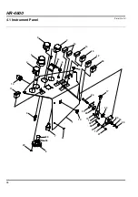
Страница 158: ...34 3 2 14 13 12 33 14 30 34 8 28 5 4 10 11 9 7 35 36 29 6 31 1 10 24 22 23 19 16 32 17 23 26 21 15 27 20 18 25 HR 4600 4 1 Instrument Panel Serial No All ...

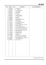
Страница 159: ...6670 1 Horn 11 3006434 1 Switch Rocker 12 3006440 1 Switch PTO Locking 13 3006436 1 Switch Rocker 4WD Only 14 3006509 3 Plug Hole 15 1002810 1 Bracket Throttle 16 3006036 1 Lever Throttle 17 366768 1 Knob 18 452008 1 Washer 3 8 Flat 19 558020 1 Swivel 20 351956 1 Spring Compression 21 558021 1 Clip Conduit 22 3006035 1 Plate Friction 23 360885 2 Washer Friction 24 400272 1 Screw 3 8 16 x 2 1 4 Hex...

Страница 160: ...36 26 25 3 18 4 5 12 27 9 20 27 26 8 2 1 13 2 11 21 14 16 7 30 26 17 15 24 19 27 23 29 23 27 14 21 27 22 6 10 28 22 27 6 28 HR 4600 5 1 Hydro Pedal Serial No All ...

Страница 161: ... 13 471214 1 Fitting Grease 14 446136 2 Lockwasher 5 16 Heavy 15 446110 2 Lockwasher 8 16 403860 2 Screw 8 32 x 5 8 Truss Head 17 453004 2 Washer 8 Flat 18 444718 1 Locknut 5 16 18 Center 19 400272 1 Screw 3 8 16 x 2 1 4 Hex Head 20 445795 6 Nut 5 16 18 Spiralock Flange 21 400182 4 Screw 5 16 18 x 5 8 Hex Head 22 443112 2 Nut 3 8 24 Hex 23 452008 2 Washer 3 8 Flat 24 444306 2 Nut 8 32 Hex 25 30026...

Страница 162: ...38 19 21 22 23 1 15 14 16 8 8 8 8 9 7 6 16 25 25 20 9 4 18 13 3 13 18 12 14 10 17 24 2 11 12 13 18 15 26 27 28 5 HR 4600 6 1 Brake Pedal Serial No All ...

Страница 163: ... Truss Head 12 1002984 2 Pedal Turn Asst 13 444718 4 Locknut 5 16 18 Center 14 445795 8 Nut 5 16 18 Spiralock Flange 15 441602 8 Bolt 5 16 18 x 3 4 Carriage 16 400182 2 Screw 5 16 18 x 5 8 Hex Head 17 444306 4 Nut 8 32 Hex 18 400188 2 Screw 5 16 18 x 1 Hex Head 19 1003504 2 Brake Spring Assembly 20 3008383 1 Clip Wire Harness 21 443812 2 Nut 3 8 24 Hex Jam 22 461451 2 Clevis Pin 5 16 x 15 16 23 46...

Страница 164: ...40 HR 4600 7 1 Frame and Front Axle Serial No All 1 2 3 4 5 6 7 9 11 12 13 14 15 16 17 18 19 20 21 22 23 24 25 26 27 28 16 17 8 10 ...

Страница 165: ...ration 33 1 12 1 Brake Assembly See Illustration 33 1 13 2000141 2 Hub Wheel 14 3007862 2 Spring Extension 15 340486 2 Brake Disk 16 446154 8 Lockwasher 1 2 Heavy 17 400410 8 Screw 1 2 13 x 1 3 4 Hex Head 18 353914 12 Bolt Wheel 19 400108 16 Screw 1 4 20 x 3 4 Hex Head 20 400612 4 Screw 5 8 11 x 1 1 2 Hex Head 21 446166 4 Lockwasher 5 8 Heavy 22 443126 4 Nut 5 8 11 Hex 23 453020 4 Washer 5 8 Flat ...

Страница 166: ...42 34 38 37 35 36 37 14 11 12 24 7 4 9 6 9 4 5 4 28 29 26 25 32 1 33 3 2 15 20 22 19 25 32 26 31 29 31 30 23 21 18 17 15 10 20 15 27 9 8 9 15 17 13 16 16 HR 4600 8 1 2 Wheel Drive Steering Serial No All ...

Страница 167: ... 18 x 1 3 4 444718 2 Locknut 5 16 18 Hex 471214 2 Grease Fitting 17 445666 2 Nut 1 2 20 Slotted Hex 18 1002032 1 Ball Joint Right Hand 19 1002031 1 Ball Joint Left Hand 471214 2 Grease Fitting 20 445647 2 Nut 3 8 24 Slotted Hex 21 443120 1 Nut 1 2 20 Hex 22 445664 1 Nut 1 2 20 Hex Left Hand Thread 23 3009378 1 Tie Rod 24 471227 1 45 Grease Fitting 25 460050 2 Cotter Pin 3 16 x 1 1 4 26 445710 2 Nu...

Страница 168: ...42 34 38 37 35 36 37 14 11 12 24 7 4 9 6 9 4 5 4 28 29 26 25 32 1 33 3 2 15 20 22 19 25 32 26 31 29 31 30 23 21 18 17 15 10 20 15 27 9 8 9 15 17 13 16 16 HR 4600 8 1 2 Wheel Drive Steering Serial No All ...

Страница 169: ... 18 x 1 3 4 444718 2 Locknut 5 16 18 Hex 471214 2 Grease Fitting 17 445666 2 Nut 1 2 20 Slotted Hex 18 1002032 1 Ball Joint Right Hand 19 1002031 1 Ball Joint Left Hand 471214 2 Grease Fitting 20 445647 2 Nut 3 8 24 Slotted Hex 21 443120 1 Nut 1 2 20 Hex 22 445664 1 Nut 1 2 20 Hex Left Hand Thread 23 3009378 1 Tie Rod 24 471227 1 45 Grease Fitting 25 460050 2 Cotter Pin 3 16 x 1 1 4 26 445710 2 Nu...

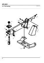
Страница 170: ...46 HR 4600 10 1 Tilt Steering Serial No All 1 2 3 4 5 6 7 8 9 10 11 12 13 14 15 16 17 18 19 20 21 4 11 11 ...

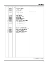
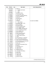
Страница 171: ...2 Bolt Shoulder 8 3005981 1 Bracket Steering Pump 9 366822 1 Cap Steering Wheel 10 400192 1 Screw 5 16 18 x 1 1 2 Hex Head 11 444718 3 Locknut 5 16 18 Center 12 444849 2 Locknut 3 4 10 Center Jam 13 444754 4 Locknut 5 16 24 Center 14 447224 1 Lockwasher 5 8 Internal 15 400216 1 Screw 5 16 18 x 2 3 4 Hex Head 16 445795 6 Nut 5 16 18 Spiralock Flange 17 416911 2 Screw 10 24 x 1 2 Thread Cutting 18 4...

Страница 172: ...tor and Air Cleaner Serial No All 1 2 3 4 5 6 7 8 9 10 11 12 13 14 15 16 17 18 19 20 21 22 23 24 25 26 27 28 29 30 31 32 33 34 35 36 37 38 39 37 35 35 35 35 34 34 34 34 34 34 34 33 33 25 25 25 25 24 23 23 23 22 21 21 21 40 ...

Страница 173: ... 15 5003447 1 Hose Radiator Overflow Bulk 16 3006634 1 Hose Air Cleaner to Engine 17 3006632 1 Hose Radiator Inlet 18 3005609 1 Mount Oil Cooler 19 358971 2 Block Rubber Mounting 20 365398 1 Indicator Air Cleaner 21 444718 1 Locknut 5 16 18 Center 22 345666 2 Clamp 23 400188 8 Screw 5 16 18 x 1 Hex Head 24 445796 6 Nut 3 8 16 Spiralock Flange 25 400182 13 Screw 5 16 18 x 5 8 Hex Head 26 400200 2 S...

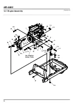
Страница 174: ...50 HR 4600 12 1 Engine Assembly Serial No All 1 2 3 4 5 6 7 8 9 10 11 12 13 14 15 16 17 18 19 20 21 22 23 24 25 2 16 17 20 20 21 22 24 24 26 Ref Negative Battery Cable 27 28 29 30 29 ...

Страница 175: ...w 1 4 20 x 3 4 Hex Head 13 445794 1 Nut 1 4 20 Spiralock Flange 14 444718 1 Locknut 5 16 18 Center 15 452006 3 Flat Washer 5 16 16 363485 10 Lockwasher M10 Heavy 17 366884 9 Screw M10 1 25 x 20mm Hex Head 18 362263 2 Screw M10 1 25 x 25mm Hex Head 19 361695 2 Screw M80 1 25 x 110mm Hex Hd 20 400188 7 Screw 5 16 18 x 1 Hex Head 21 400272 3 Screw 3 8 16 x 2 1 4 Hex Head 22 444762 3 Locknut 3 8 16 Ce...

Страница 176: ...s 1 1002931 1 Muffler 2 1004598 1 Tailpipe 3 363586 6 Screw M8 1 25 x 20mm Hex Head 4 452006 2 Flat Washer 5 16 5 363485 2 Lockwasher M10 Heavy 6 362263 2 Bolt M10 1 25 x 25mm Hex Head 7 446136 6 Lockwasher 5 16 Heavy 8 553020 1 Gasket Exhaust 9 348856 1 Clamp Exhaust 10 3007889 1 Sleeve Insulating 1 2 3 4 5 6 7 8 9 10 3 7 ...

Страница 177: ... 446154 2 Lockwasher 1 2 Heavy 6 443118 2 Nut 1 2 13 Hex 7 363485 3 Lockwasher M10 Heavy 8 362263 3 Screw M10 1 25 x 25mm Hex Head 9 444762 5 Locknut 5 16 18 Center 10 452008 2 Flat Washer 3 8 11 446142 2 Lockwasher 3 8 Heavy 12 362743 1 O Ring Seal 13 400266 2 Screw 3 8 16 x 1 1 2 Hex Head 14 400410 2 Screw 1 2 13 x 1 3 4 Hex Head 15 400264 2 Screw 3 8 16 x 1 1 4 hex Head 16 2809907 2 Nut M10 Spi...

Страница 178: ...Serial No All 1 2 3 4 5 6 7 8 9 10 11 12 13 14 15 16 17 18 19 20 21 22 23 24 25 26 27 28 29 30 31 32 33 34 35 36 37 38 39 40 41 42 43 44 45 2 5 7 8 10 11 14 14 15 15 18 19 20 20 21 22 23 23 24 25 25 26 27 28 29 30 31 38 22 Part of Frame ...

Страница 179: ... 19 401028 6 Screw 3 8 16 x 3 1 4 Hex Head 20 443102 6 Nut 1 4 20 Hex 21 443110 8 Nut 3 8 16 Hex 22 444762 6 Locknut 3 8 16 Center 23 446130 6 Lockwasher 1 4 Heavy 24 446142 8 Lockwasher 3 8 Heavy 25 452008 12 Flat Washer 3 8 26 452004 4 Flat Washer 1 4 27 3007392 2 Switch Proximity 28 403860 4 Screw 8 32 x 5 8 Truss Head 29 446110 4 Lockwasher 8 30 444306 4 Nut 8 32 Hex 31 362824 4 Spacer Lift Ar...

Страница 180: ... 23 24 25 26 27 28 29 20 20 20 20 19 19 19 7 16 16 16 16 19 17 1 2 3 6 7 8 12 11 14 15 32 17 18 19 20 21 22 9 14 16 30 31 11 29 19 32 30 20 9 10 18 15 Detail View HR 4600 16 1 Lift Arms Continued Serial No All ...

Страница 181: ...74 2 Screw 3 8 16 x 2 1 2 Hex Head 14 471221 2 Fitting 90 Grease 15 443102 4 Nut 1 4 20 Hex 16 443110 9 Nut 3 8 16 Hex 17 444762 3 Locknut 3 8 16 Center 18 446130 2 Lockwasher 1 4 Heavy 19 446142 8 Lockwasher 3 8 Heavy 20 452008 10 Flat Washer 3 8 Heavy 21 362824 1 Spacer Lift Arm 22 323016 1 Fitting 90 Grease 23 340525 2 Bracket Guide Wheel 24 3010653 1 Bracket Left Side Guide Wheel 25 3010654 1 ...

Страница 182: ...onnect to engine fuel injector overflow Connect to engine fuel pump HR 4600 17 1 Fuel and Hydraulic Tanks Serial No All 1 2 3 4 5 6 7 8 9 10 11 12 13 14 15 16 17 18 19 20 21 22 23 7 15 15 18 18 18 18 18 19 22 23 24 ...

Страница 183: ...32 1 Filter Breather 10 3006337 1 Sender Fuel 11 5003374 1 Gasket 12 3006067 1 Cap Fuel Tank 13 554748 1 Line 5 16 I D Fuel Cut to 65 Inches 14 554748 1 Line 5 16 I D Fuel Cut to 18 Inches 15 361117 3 Bushing Fuel Tank 16 361748 1 Valve Overflow 17 554752 1 Line 3 16 I D Fuel Cut to 65 Inches 18 366526 6 Clamp Hose 19 400106 14 Screw 1 4 20 x 5 8 Hex Head 20 403910 5 Screw 10 24 x 1 2 Truss Head 2...

Страница 184: ...ription Serial Numbers Notes 1 1003439 1 Hose Pump To Upper Traction Tube 2 339994 4 Adapter Straight 3 339999 2 Adapter Straight 4 1004445 1 Hose Pump To Lower Traction Tee 5 340339 1 Tee Union 6 1003810 2 Hose Motor Port To Tee 7 1003812 2 Tube Motor Port To Tee 8 1003814 1 Tube Upper Tration Tee 9 339925 1 Cap Tube 1 2 3 4 5 6 7 8 2 2 2 3 6 7 9 ...

Страница 185: ...99 2 Adapter Straight 4 1003813 1 Tube Reverse 4WD Tee 5 1003439 1 Hose Pump To Forward 4WD Tee 6 1003814 1 Tube Forward 4WD Tee 7 1003810 2 Hose Tee To Wheel Motor 8 1003812 2 Tube Tee To Wheel Motor 9 1002622 1 Valve 4WD See Illustration 38 1 10 1003094 1 Tube Forward 4WD Tee To Valve 11 1003095 1 Tube Reverse 4WD Tee To Valve 12 1003455 4 Hose 4WD Valve To Motors 13 339989 4 Adapter Straight 1 ...

Страница 186: ... Adapter Straight 6 1004651 1 Tube Lift Valve To Junction 7 1003374 1 Tube Junction to Filter 8 1004103 1 Tube Case Drain 9 363030 3 Cover Dust 10 1003342 1 Hose LT Port To Steering Cylinder 11 1003341 1 Hose RT Port To Steering Cylinder 12 1004112 1 Hose Gear Pump To In Port 13 1004111 1 Hose Aux Port To Lift Valve P Port 14 1004110 1 Hose Out Port To Lift Valve T Port 15 339984 2 Adapter Straigh...

Страница 187: ...008745 2 Hose Gear Pump Inlet 7 340070 1 Adapter 90 8 364190 1 Clamp 1 1 2 I D 9 400264 1 Screw 3 8 16 x 1 1 4 Hex Head 10 3008673 4 Clamp Constant Torque 11 1004116 1 Hose Pump to Left Deck Valve 12 1004119 1 Hose Pump to Right Deck Valve 13 1004128 1 Hose Pump to Center Deck Valve 14 345666 1 Clamp 1 2 I D 15 453023 1 Flat Washer 1 4 16 446128 1 Lockwasher 1 4 17 400104 1 Screw 1 4 20 x 1 2 Hex ...

Страница 188: ...be Return Filter 3 1004129 1 Hose Center Deck Valve Return 4 339999 3 Adapter Straight 5 1003454 1 Hose Oil Cooler 6 1003389 1 Tube Oil Cooler 7 1004011 1 Tube Return Requires 339921 for 2WD Units 8 1004117 2 Hose Wing Deck Valve Return 9 340066 3 Adapter 90 10 1004018 1 Tube 4WD Valve Drain 4WD Only 11 339979 1 Adapter Straight 4WD Only 1 2 3 4 5 6 7 8 8 9 10 11 4 9 9 ...

Страница 189: ...6419 1 Charge Pressure Switch 2 132704 1 Return Filter 557772 1 Oil Filter Cartridge 3 3007290 1 Bracket Filter 4 409811 4 Screw 5 16 18 x 5 8 Thread Cutting 5 446130 2 Lockwasher 1 4 Heavy 6 446142 4 Lockwasher 3 8 Heavy 7 400258 4 Screw 3 8 16 x 3 4 Hex Head 8 400108 2 Screw 1 4 20 x 3 4 Hex Head 9 1003612 1 Lift Valve See 32 1 10 365466 1 Fitting Diagnostic 11 363030 1 Cover Dust 1 2 3 4 6 7 8 ...

Страница 190: ...66 HR 4600 24 1 Lift Hydraulics Serial No All 1 2 3 4 5 6 7 8 9 10 11 12 1 1 2 2 2 2 2 4 5 6 13 13 13 13 14 14 14 ...

Страница 191: ...04 2 Hose Bulkhead to Wing Cylinder 6 1004105 2 Hose Bulkhead to Wing Cylinder 7 1004108 1 Hose Lift Valve to Bulkhead Left Wing 8 1004109 1 Hose Lift Valve to Bulkhead Right Wing 9 1004124 1 Hose Return Tube to Lift Valve 10 1004133 1 Hose Lift Valve to Center Cylinder 11 1004135 1 Hose Center Cylinder to Return 12 1004246 1 Tube Bulkhead to Bulkhead 13 339961 4 Nut Bulkhead 14 3000953 3 Disc Ori...

Страница 192: ...on Serial Numbers Notes 1 445795 4 Nut 5 16 18 Spiralock Flange 2 3008474 2 Clamp 1 I D 3 400122 1 Screw 1 4 20 x 2 1 4 Hex Head 4WD Only 4 365566 2 Clamp 1 1 4 I D 5 400108 1 Screw 1 4 20 x 3 4 Hex Head 2WD Only 6 367186 1 Clamp Double Tube 7 400188 4 Screw 5 16 18 x 1 Hex Head 8 364190 1 Clamp 1 1 2 I D 9 3007558 1 Clamp Double Hose 10 409811 1 Screw 5 16 18 x 5 8 Thread Cutting 11 444708 1 Lock...

Страница 193: ...se Motor Bulkhead to Drain Tube 6 339972 1 Adapter Straight 7 1004122 2 Hose Motor Drain to Motor Bulkhead 8 340214 1 Adapter Bulkhead Tee 9 3009804 1 Bracket Motor Drain Bulkhead 10 400188 1 Screw 5 16 18 x 1 Hex Head 11 445795 1 Nut 5 16 18 Spiralock Flange 12 REF 1 Hose Left Wing Deck Motor Drain See 29 1 13 REF 1 Hose Right Wing Deck Motor Drain See 29 1 14 339961 1 Nut Bulkead 15 339960 2 Nut...

Страница 194: ...To Gear Pump To Gear Pump HR 4600 27 1 Wing Deck Control Valves Serial No All Item Part No Qty Description Serial Numbers Notes 1 340264 2 Adapter Tee 2 452004 8 Flat Washer 1 4 3 446128 4 Lockwasher 1 4 4 443102 4 Nut 1 4 20 Hex 5 400122 4 Screw 1 4 20 x 2 1 4 Hex Head 6 1004137 2 Valve Deck Control 7 339984 2 Adapter Straight 8 351127 2 Plug 1 2 3 4 5 6 7 8 1 2 6 7 ...

Страница 195: ...1 Adapter Tee 2 452004 4 Flat Washer 1 4 3 3008508 1 Bracket Valve Mount 4 446128 2 Lockwasher 1 4 5 443102 2 Nut 1 4 20 Hex 6 400122 2 Screw 1 4 20 x 2 1 4 Hex Head 7 446134 2 Lockwasher 5 16 8 443106 2 Nut 5 16 18 Hex 9 400184 2 Screw 5 16 18 x 3 4 Hex Head 10 1004137 1 Valve Deck Control 11 339984 1 Adapter Straight 12 351127 1 Plug 13 340376 1 Adapter 90 14 15 1 2 3 4 5 6 7 8 9 10 11 12 13 2 ...

Страница 196: ... Notes 1 340055 2 Adapter 90 2 1004113 2 Hose Deck Valve to Inside Motor REFERENCE A See 27 1 3 1004114 2 Hose Inside Motor to Outside Motor 4 1004115 2 Hose Deck Valve to Outside Motor REFERENCE B See 27 1 5 1004120 2 Hose Inside Motor to Outside Motor 6 1004121 2 Hose Wing Deck Motor Drain 7 339989 8 Adapter Straight 8 340095 2 Adapter Tee 9 473142 AR Cable Tie 1 2 3 4 5 6 7 8 7 7 7 ...

Страница 197: ...90 2 1004642 1 Hose Deck Valve to Left Motor REFERENCE C See 28 1 3 1004643 1 Hose Deck Valve to Right Motor 4 1004644 1 Hose Left Motor to Right Motor REFERENCE D See 28 1 5 340095 1 Adapter Tee 6 1004648 1 Hose Left Motor to Right Motor 7 1004131 1 Hose Center Deck Case Drain 8 340033 4 Adapter 45 9 473142 AR Cable Tie 30 1 Center Deck Serial No 1 2 3 4 5 6 7 8 8 8 8 ...

Страница 198: ...Plugs G Fuel Solenoid H Charge Filter Switch J Engine Oil Pressure Switch K Temperature Sender L 4WD Valve 4WD Only M Deck Valve 3 AMP 20 AMP 25 AMP 3 AMP Fuse Locations Top HR 4600 31 1 Wire Harness and Controller Box Serial No All 1 4 3 22 2 7 8 9 10 11 13 14 15 16 18 19 20 23 24 25 12 17 21 26 27 8 8 10 10 11 P O 14 16 16 17 P O 21 26 12 9 5 6 28 ...

Страница 199: ...3A Diode 5003276 2 3 Amp Fuse 5003282 1 20 Amp Fuse 5003283 1 25 Amp Fuse 3009728 8 Harness Solenoid Not Shown 15 361439 1 Circuit Breaker 12V 50A 16 446118 7 Lockwasher 10 17 403910 5 Screw 10 24 x 1 2 Truss Head 18 3001307 3 Relay SPDT With Resistor 19 3006509 1 Plug Hole 20 3007777 1 Cable Positive Battery 21 3007776 1 Cable Negative Battery 22 443106 4 Nut 5 16 18 Hex 23 3009251 1 Tab Wire Har...

Страница 200: ...l Item Part No Qty Description Serial Numbers Notes 1 5003757 1 Relief Valve 2 5002913 1 Solenoid Valve 3 5001353 1 Solenoid Valve 4 5003758 3 Solenoid Valve 5 5003759 3 Solenoid Valve 6 5002157 5 Plug Port 7 5001065 2 Plug Port 8 5003508 6 Coil 9 5003507 2 Coil 7 4 8 5 8 1 2 9 3 9 6 6 5 8 ...

Страница 201: ...otes 1 5001354 2 Coil 2 5003096 1 Solenoid Valve 5003578 1 Solenoid Valve Seal Kit 3 5003121 1 Solenoid Valve 5003554 1 Solenoid Valve Seal Kit 4 5003097 1 Pilot Operated 2 Way 5003580 1 2 Way Seal Kit 5 5003098 1 Check Valve 5003579 1 Seal Kit 6 5003099 1 Relief Velve 5003579 1 Seal Kit 7 5001065 4 Plug Port 8 5002541 15 Plug Port 1 1 2 3 4 5 6 7 7 7 8 8 8 8 8 8 8 8 8 ...

Страница 202: ...78 HR 4600 34 1 Steering Valve Part Number 1003458 Serial No All 1 2 3 4 5 6 7 8 10 9 11 12 13 14 15 16 17 18 19 20 21 22 23 24 25 26 27 28 29 31 32 33 34 35 36 37 4 4 4 11 11 38 30 ...

Страница 203: ...solation Manifold 16 N S 1 Drive Link 17 N S 1 Metering Ring 18 A 11 Screw Socket Head 19 C 1 Seal Commutator 20 A 1 Commutator Cover 21 A 1 Commutator RIng 22 A 1 Commutator 23 A 1 Spacer 24 A 1 Rotor 25 A 1 Stator 26 A 1 Drive Plate 27 554855 1 Spacer 28 554856 1 Thrust Bearing 29 C 1 Face Seal 30 N S 1 Ball 9 32 31 554857 1 Seal Spacer 32 N S 1 Upper Cover Plate 33 D 1 Shaft 34 D 1 Retaining RI...

Страница 204: ...g Kit 4 554779 1 Nut Hex 5 554780 1 Key 6 558064 1 Bearing Housing 7 557629 1 Drive 8 557630 1 Geroler 9 557632 1 Drive Valve 10 557631 1 Plate Valve 11 557633 1 Valve 12 557637 1 Balance Ring and Pins 13 557634 1 Seal Inner Face 14 557635 1 Seal Outer Face 15 557636 2 Spring 16 557650 3 Bolt 5 3 4 17 557638 1 Housing Valve 18 557639 2 Check Plug Assembly 19 557642 2 Spring 20 557640 2 Ball Steel ...

Страница 205: ... Part No Qty Description Serial Numbers Notes 1 A 1 Seal Exclusion 2 A 4 Seal 3 I D 3 A 1 Back Up Ring 4 A 1 Shaft Seal 5 5003384 1 Shaft and Bearing Kit 6 554780 1 Key 7 554779 1 Hex Nut 8 A 1 Shaft Face Seal 9 A 1 Inner Face Seal 10 A 1 Outer Face Seal 11 556450 4 Bolt 5003385 1 Seal Kit Includes Items Marked A 1 2 3 4 5 6 7 8 9 10 11 2 2 2 ...

Страница 206: ...rake Mounting 503308 1 Disk Brake R H 503309 1 Disk Brake L H 2 590259 4 Nut 3 8 24 3 549441 2 V Plate 4 503306 1 Cam Lever Used on 503308 Only 4 502517 1 Cam Lever Used on 503309 Only 5 503296 2 Stud Plate with Lining 6 546131 4 Spring 7 554579 4 Spacer Brake 8 503295 2 Rib Plate with Lining 9 590260 4 Screw 3 8 24 x 2 1 4 1 2 3 4 5 6 7 8 9 2 6 7 ...

Страница 207: ...vious revision HR 4600 38 1 Deck Valve Part Number 1004137 Serial No All Item Part No Qty Description Serial Numbers Notes 1 N S 1 Manifold 2 5003508 1 Coil 3 5003747 1 Solenoid Valve 5002540 1 Seal Kit Deck Valve 1 2 3 ...

Страница 208: ...Serial No All Item Part No Qty Description Serial Numbers Notes 1 555892 1 Seat Belt Assy 2 400374 1 Screw 7 17 20 x 1 1 2 Hex Hd 3 452010 3 Washer 7 16 Flat Wide 4 446148 2 Lockwasher 7 16 Hvy 5 400370 1 Screw 7 16 20 x 1 Hex Hd 6 5000465 8 Screw GR8 Hex Cap 7 446154 8 Lockwasher 1 2 Hvy ...

Страница 209: ...N COUNTER CLOCKWISE BLADE ROTATION ON THE DECK ONLY BLADE BOLTS ARE L H THREAD 5 5 5 5 5 5 Serious injury or death can result from blade contact or from objects being thrown very long distances Do not operate machine with discharge chute or guards flipped up or removed Do not operate machine with bent components or with implement in raised position Keep yourself and others away from the mower when...

Страница 210: ...86 1 3 30 4 6 9 10 11 2 20 25 26 27 12 17 18 19 16 22 23 21 24 22 23 21 28 7 13 29 29 14 15 8 HR 4600 41 1 Wing Decks Left Wing Shown Serial No All ...

Страница 211: ...4 Locknut 3 4 16 Hex Jam UNF 13 3010387 6 4 Plate Caster Fork 14 440124 12 Carriage Bolt 3 8 16 x 1 3 4 15 400260 8 Screw 3 8 16 x 7 8 Hex Hd 16 1004926 2 Motor Spindle L H Left Wing Deck Only 16 1004925 2 Motor Spindle R H Right Wing Deck Only 5003763 1 Kit Seal 17 471214 2 Fitting Grease 18 400410 2 Screw 1 2 13 x 1 3 4 Hex Hd Left Wing Deck Only 18 401237 2 Screw 1 2 13 x 1 3 4 Hex Hd L H Right...

Страница 212: ...88 4 6 7 8 9 5 14 17 18 19 20 23 21 13 15 16 22 16 10 11 11 1 12 25 26 24 3 2 27 31 28 29 34 33 30 32 30 31 30 HR 4600 42 1 Wing Decks Continued Left Wing Shown Serial No All ...

Страница 213: ... 7 1 Housing Pivot 471216 4 Fitting Grease 14 340433 2 Ring Shaft 15 366484 1 Shaft Pivot Mounting 16 367601 2 Washer Thrust 17 362464 6 Bolt Wheel 18 346294 6 Nut Wheel 19 460084 1 Cotter Pin 3 8 x 1 1 2 20 400194 1 Screw 5 16 18 x 1 3 4 Hex Head 21 446136 1 Lockwasher 5 16 22 366593 AR Spacer 23 443106 1 Nut 5 16 18 Hex 24 444708 1 Locknut 1 4 20 Center 25 367186 1 Clamp 2 Hose 26 400122 1 Screw...

Страница 214: ...90 1 2 3 4 5 6 7 36 34 35 8 9 10 11 12 13 14 15 16 17 18 19 22 20 21 23 21 22 22 24 25 26 28 28 32 27 30 29 30 31 33 HR 4600 43 1 Rear Deck Serial No All ...

Страница 215: ...60084 4 Pin Cotter 3 8 x 1 1 2 16 403578 4 Screw 10 24 x 1 Hex Hd 17 444310 4 Nut 10 24 Hex 18 446118 4 Lockwasher 10 Hvy 19 440124 12 Bolt 3 8 16 x 1 3 4 Carriage 20 453011 12 Washer 3 8 Flat 21 446142 22 Lockwasher 3 8 Hvy 22 443110 22 Nut 3 8 16 Hex 23 402690 8 Screw 3 8 16 x 1 3 4 SL FL Hd 24 446140 6 Lockwasher 3 8 25 207485 1 Housing Reel Pivot 471216 4 Grease Fitting 45 26 366593 1 Spacer C...

Страница 216: ...erial No All Item Part No Qty Description Serial Numbers Notes 1 551440 2 End Cap 2 551439 2 Seal Grease 3 551437 4 Stop Washer 4 551438 2 Roller Bearing 5 471218 1 Grease Fitting 45 6 360111 1 Valve Inflation 7 5003066 1 Wheel Rim 8 551436 1 Tire 9 x 3 5 4 1 2 3 4 1 2 3 4 5 6 7 8 3 ...

Страница 217: ...nge Aerosol 546408 Twelve 1 Quart Can Orange 546409 Two 1 Gallon Can Orange Lapping Compound 5002488 One 10 Pound Pail of 80 Grit 5002490 One 25 Pound Pail of 80 Grit 5002489 One 10 Pound Pail of 120 Grit 5002491 One 25 Pound Pail of 120 Grit Specialty Compound 365422 5 3 Ounce Tube of Electrical Insulating Gel 5001581 14 Ounce Can of Lubriplate Multi Lube A Biodegradable 5003102 One 55 Gallon Dru...

Страница 218: ... B 1 Battery CB 1 Circuit Breaker F 1 3 Amp Fuse F 2 20 Amp Fuse F 3 25 Amp Fuse F 4 3 Amp Fuse K 1 Glow Plug Relay K 2 Fuel Solenoid K 3 4WD Solenoid K 4 Starter Relay K 5 LW Lift Solenoid K 6 C Lift Solenoid K 7 RW Lift Solenoid K 10 Cruise Solenoid K 11 RW Mow Solenoid K13 LW Mow Solenoid K15 RW Lower Solenoid K16 C Lower Solenoid K17 LW Lower Solenoid K 18 Lift Pressure Solenoid K 19 Ignition ...

Страница 219: ...DB Bn Bu Bn Og Gy Wh Pu Pk Bn Bu Bn Og Gy Wh Pu Pk Gy Ye Gy Ye DB Ye Gn Rd DB Og Gn Rd DB Rd DB Rd Og Pk Og Pk Og Pk DB Ye DB Og Og Pk Og Pk Og Pk Og Pk Og Pk Og Pk Og Pk Og Pk Og Pk Og Pk Og Pk Og Pk Og Pk Gy Wh Gy Wh Gy Gy 2 11 2 3 3 2 3 12 3 1 Select 3 Select 2 Select 1 Spare Input Ls Lw Ls Fl Ls Fr Ls Rw Rw Lw Lower Raise Mow Rw R Mow Rw F Mow C R Mow C F Mow Lw R Mow Lw F Backlap Transport Oi...

Страница 220: ...3 ci 0 43 ci 0 43 ci Displacement Control Tow Valve Reverse Diag Forward Diag 3000 RPM 5 ci A B Traction Pump Gear Pump Center Deck Motors Left Wing Deck Motors Right Wing Deck Motors Strg Diag 10 Micron 25 psi Crack Bypass 30 psi Crack Bypass 100 Mesh Screen Return Filter Oil Cooler A B C D E F Right Wing Deck Valve Left Wing Deck Valve Center Deck Valve HR 4600 46 1 Hydraulic Schematic Serial No...

Страница 221: ...r Right Wing Cylinder Steering Unit In Out Aux LT RT 4 13 ci 1450 psi 25 psi 25 psi 10 Micron Charge Filter 19 0 ci 19 0 ci Front Wheel Motors 4WD Valve Rear Wheel Motors 450 psi 8 0 ci 8 0 ci 1 1 2 2 F R Lift Diag A B C D E F P G SO C 1 2 3 Lift Valve 200 psi HR 4600 ...

Страница 222: ......
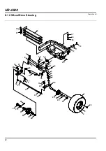
Страница 223: ...product in California USA and is as required by proposition 65 CALIFORNIA Proposition 65 Warning Diesel engine exhaust and some of its constituents are known to the State of California to cause cancer birth defects and other reproductive harm GB ...

Страница 224: ...erzekerd door de ISO 9001 registratie die op al onze productielocaties van toepassing is Een wereldwijd dealernet en technici met een fabriekopleiding voorzien mede dankzij de back up van Ransomes Jacobsen Parts Xpress in een betrouwbare productondersteuning van hoge kwaliteit Kwaliteit prestatie en ondersteuning van wereldklasse Geräte der Firma Ransomes Jacobsen Limited werden nach höchst anspru...

Отзывы: