Installation manual: OASiS security system JA-82KRC
1 / 21
MKH51100_OS2
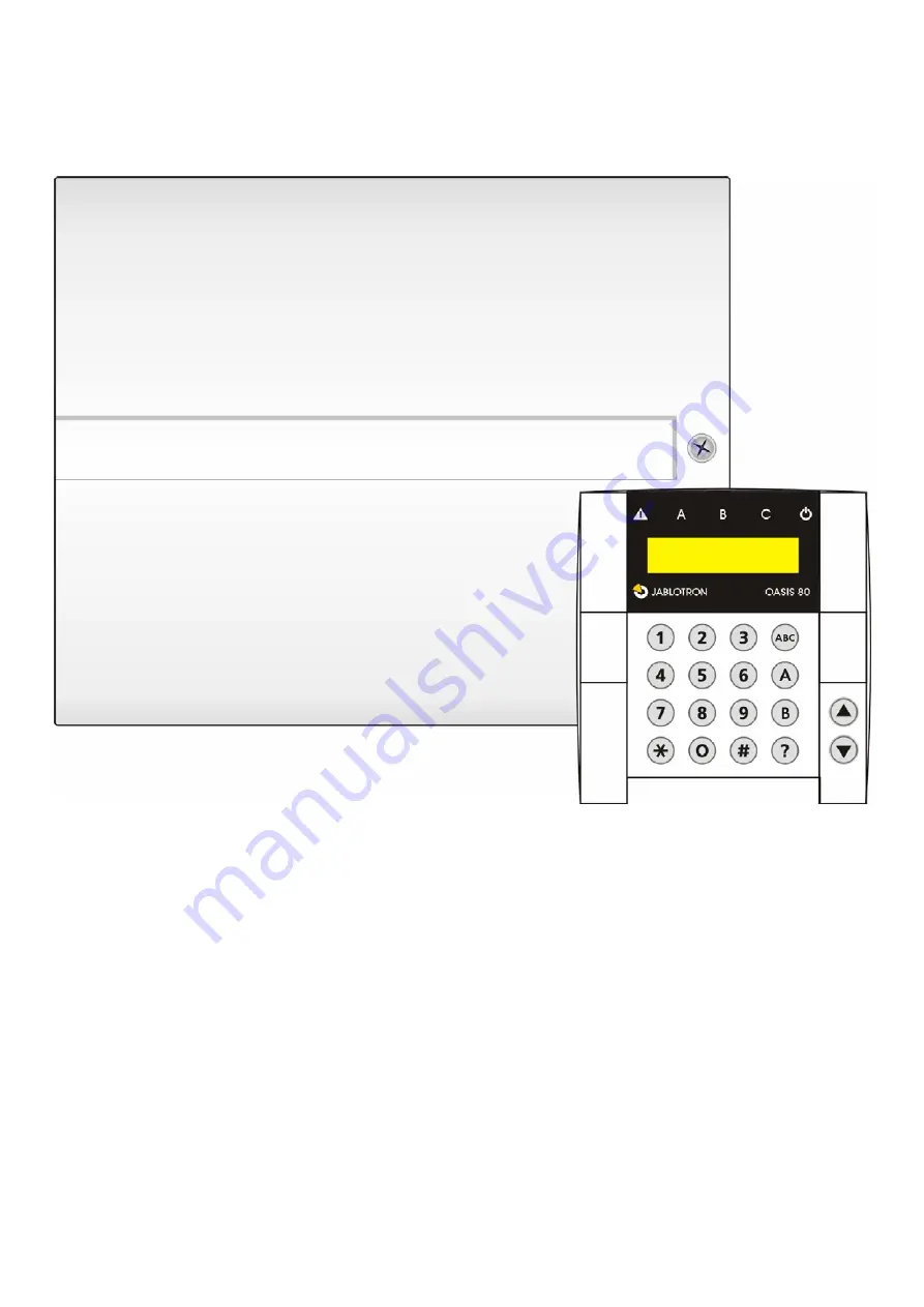
JA-82KRC “OASiS”
Control panel installation manual
This manual is valid for control panel JA-82KRC. The control panel can be configured by a PC running OLink software.
Страница 1: ...nual OASiS security system JA 82KRC 1 21 MKH51100_OS2 JA 82KRC OASiS Control panel installation manual This manual is valid for control panel JA 82KRC The control panel can be configured by a PC running OLink software ...
Страница 2: ...dible alarms 13 12 21 Wireless siren alarm enabled IW and EW 13 12 22 Auto bypass user approval via the key 13 12 23 Final door detectors 13 12 24 Partial setting arming or system splitting 14 12 25 Automatic summer time daylight saving time 14 12 26 Tamper alarm in response to an increase in the number of triggered tamper sensors 14 12 27 Operating the PG outputs using 8 and 9 14 12 28 Permanent ...
Страница 3: ...e control panel does not allow for the simultaneous connection of both a wired and a wireless input to the same address Connecting to a wired input automatically disables the wireless input of the same address o Other hard wired inputs are provided by some wireless devices such as keypads door detectors and PIR movement detectors 1 1 Main features When triggered a detector or any other device conn...
Страница 4: ...or Maintenance modes 1 2 Optional system configurations In the European Union region follow the valid standards and rules especially series EN 501 xx The Oasis control panel complies with grade 2 The control panel must have one of the following configurations as a minimum At least two non backup battery sirens JA 80L or SA 105 communicator class ATS2 JA 80Y JA 80V or JA 80X At least one backup bat...
Страница 5: ... parallel resistors see the diagram below o For wiring examples see the below diagram TAMPER SIREN ACTIVATION TAMPER ACTIVATION TAMPER ACTIVATION TAMPER ACTIVATION ACTIVATION DOOR 1 DOOR 2 DETECTOR 1 DETECTOR 2 DETECTOR 3 Maximum of 5 detectors in one loop If you enroll a wireless device to address 01 to 04 the corresponding input terminal will be disabled o The same applies to input terminals 05 ...
Страница 6: ...e control panel for 1 second e g using a screwdriver This will enter enrollment mode on the control panel 4 Install batteries into the keypad not far from the control panel 5 The keypad generates a beep sound and enrolls to address 05 or 15 After that it indicates Enrollment 06 Device or Enrollment 16 Device 6 Press the key to exit enrollment mode and Service will be indicated on the keypad Warnin...
Страница 7: ...onnection to the control panel possibly due to excessive distance or it could be too close to the control panel closer than 2 meters is not permitted To re enroll a device first disconnect its battery Then wait about 10 seconds or to save time press and release its tamper switch to quickly discharge any remaining energy A sub control panel can be enrolled to a master control panel by keying in the...
Страница 8: ...ne multiple control panels in one UC or AC receiver 12 Control panel programming The most convenient way to program the system is to use a PC running OLink software The system can however also be programmed by keying in the sequences in section 12 1 The system should be in Service mode if not enter the following with the system unset 0 Service code the factory default is 8080 Enter the appropriate...
Страница 9: ...ng Entrance delay beeps 35x 351 YES 350 NO YES Setting arming confirmation by wired siren chirp 36x 361 YES 360 NO NO IW terminal only Siren always sounds during audible alarms 37x 371 YES 370 NO YES NO siren only sounds if the system is completely set armed Wireless siren alarms enabled IW EW 38x 381 YES 380 NO YES Auto bypass user approval via the key If a detector is active during setting armin...
Страница 10: ...as the effect or SET A or SET AB C has the effect or SET ABC or UNSET ABC In a split system a keyfob button pair assigned to section A SET UNSET A B SET UNSET B C SET UNSET ABC 61 nn r s Code card reactions and section assignment A code card may have the same kind of reaction as devices 62 nn r s nn address 01 to 50 r reaction 0 disabled incl tamper sensor 1 Natural this means for detectors select...
Страница 11: ...y alarm PG on excluding Panic Panic A PGX on Panic B PGY on 6 AC dropout PG on Fire PGX on dropout PGY on 7 ON OFF 8 2 seconds pulse The ON OFF and 2 second pulse functions can be controlled from the keypad by keying in 8 9 or using the arrow keys see 12 27 or they can be operated by a code or card These PG output functions can also controlled by signals from keyfobs or detectors see 12 41 Notes T...
Страница 12: ...aster code has no effect on other codes and cards Resets are recorded in the control panel memory and sent to the ARC if used Alarm Receiving Centre previously called a central monitoring station 12 12 Control panel enrollment to UC or AC modules or to a sub control panel Keying in 299 sends an enrollment signal to enroll the control panel to UC 82 or AC 82 receiving modules see 11 6 This sequence...
Страница 13: ...21 Wireless siren alarm enabled IW and EW This setting is for enabling and disabling wireless sirens in the system 3 8 1 wireless sirens enabled 3 8 0 wireless sirens disabled Note This setting has no effect on wired output terminals Factory default setting wireless sirens enabled 12 22 Auto bypass user approval via the key The system has a built in auto bypass function so that if any number of de...
Страница 14: ...unset immediately after the user sets unsets the system Assigning wireless devices access codes and keyfobs to various sections of the system has no effect in this mode Partial setting is especially suitable for homes and apartments where the user wishes to protect different parts of the premises during the day Detectors can be assigned to three sections A B and C Using setting arming key A on the...
Страница 15: ...her or a JA 80V version XA64005 or higher is installed 12 32 Annual check notification This sequence enables the user and installer to be notified of the necessary time for an annual technical check 6900 notification disabled 6901 notification enabled Notes An annual technical inspection notification is displayed as text on the keypad display and can also be sent as an SMS to the end user and or i...
Страница 16: ...e hard wired input terminals in the control panel or enrolled wireless devices r is the reaction index from 0 to 9 see Table 2 s is the section 1 A 2 B 3 C only has an effect if partial setting or system splitting is used except for PG output control Guidance on assignment to sections Assigning keyfobs with natural reactions to sections s button Unsplit system Partial setting Split system or set s...
Страница 17: ...rd has a natural reaction i e r 1 then its reaction is set unset set etc the same as reaction r 9 in table 2 A code card can also have an alarm reaction designated to it similar to detectors Factory default setting all codes cards from 01 to 50 have a natural reaction set unset and are assigned to section C 12 42 Enrollment by keying in production codes This sequence allow the enrollment of device...
Страница 18: ...ext is stored in the non volatile memory of keypads so power disconnection will not erase any stored text Convenient text editing is possible using a PC running OLink software Besides device names keypads also use so called internal text such as service maintenance mode etc and this text can also be edited via OLink software by selecting Settings on the menu and then keypad text After editing keyp...
Страница 19: ... codes and cards from 01 to 50 are erased If a user has both a code and a card then it is possible to program whether both a code and card must be presented to the system for system access or whether only one of them is required see 12 37 The system does not allow the same code or card to be programmed to multiple users if it is desired to move a code card to another user the card code has to be e...
Страница 20: ...0 can be scrolled through with the A indicator showing whether a code is programmed or not and the B indicator showing whether a card is programmed or not 4 To exit this code card display mode press the key 5 To exit maintenance mode press the key To change access codes and cards use sequence 6 MC nn NC see 13 2 The most convenient way to administer codes is by using a PC running OLink software 13...
Страница 21: ...control panel The wireless keypad does not indicate entrance delays by beeping If the keypad is only battery powered then it turns off 20 seconds after the last time a key was pressed To indicate entrance delays first wake it up Install an ordinary magnetic sensor to the entrance door wiring it to the keypad input so that opening the door wakes up the keypad and reports to the control panel Altern...