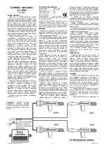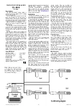
Central door locking system
CL-20A
(CL-20A2)
Description:
This electromechanical locking system is
suitable for all cars equipped with 12V voltage
and a negative ground.
The set includes two actuators for the front
doors, two actuators for the rear doors, a
control unit and a wire harness. An assortment
of mechanical components for easy installation
of the actuators to the doors is also provided.
Model CL-20A2 is a modification for cars
with only two doors (it does not include rear
door actuators).
The actuator's mechanical output should be
connected to the mechanical locking system
inside the door so that it performs the same
movements as when the locks are operated
manually.
The front door actuators are equipped with
position detectors. The position information is
processed by the control unit. If there is any
position change detected, the control unit
gives instruction to the others actuators to
make the same position change. This allows
all door locks to be operated from one point
(either of the front door locks).
The control unit can also be connected to a
remote control. Use only a car alarm or remote
control unit with “Floating Code” ability. This
type of system provides a much higher safety
level than systems with only a fix code. We
recommend to combine the central locking
system with the Jablotron car alarm model CA-
300SP or remote controller model CL-301S.
Specifications
operating voltage
10 to 15VDC
stand by consumption
max. 0.1mA
max. working current
14A
actuator force
40N
actuator range
18mm
reaction time
max. 0.3sec.
remote control inputs are sensitive to
negative signals (ground)
Complies with the essential requirements of:
89/336/EC
EMC Directive - Protection
concerning electromagnetic compatibility
when is used for its intended purpose.
Original of the conformity assessment can be
found at the web page
www.jablotron.cz
,
section Technical support.
Installation
Mechanical installation of actuators to some
car models can be complicated. Therefore we
recommend professional installation.
The actuators must be installed in such a way
that the actuator movement axis is the same
as the movement axis of the moving door lock.
The actuators with five wires are for the front
doors. Actuators with two wires are for the rear
doors. After actuator installation, check by hand
that the locks can move easily and smoothly.
Before you install the control unit, disconnect
the car battery. Then, remove the fuse from
the holder on the wire harness provided with
the system. Keep in mind that if your car has
some memory functions built in, then these
may be erased if you disconnect the battery.
Refer to the car owners' manual before
disconnecting the battery.
Install the control unit in the passenger
compartment. The recommended location is
under the dash board.
Route the wire harness cables to each door.
Be sure that the cables will not be broken when
opening or closing the door. The end of the
cables are equipped with connectors: connect
the wires so that the colors corresponds.
If one or more of the door locks require an
opposite movement of the actuator for locking,
substitute the blue wire of the corresponding
actuator for the green wire. In the case that it is
front door actuator, you also have to substitute
the brown wire for the white wire.
Positive Supply - The red wire with a fuse
holder (15A) should be connected directly to
the positive terminal of the battery cable.
Grounding - connect the black wire to the
original GND point in the car. Do not use any
temporary grounding.
Centrl door locking system CL-20A
2/2
MBY51300
Remote control - the white colored wire with
blue stripe (unlock) and the white colored
wire with black stripe (lock) are inputs for the
remote control. They are sensitive to
negative potential (connection with ground).
If you are going to connect CL-20A with a
remote control, do it after completing the
installation of the locking system and after
testing. If you do not want to use remote
control inputs, you can remove the wires
from the flat connector by pressing the
corresponding tab on the side of connector
body and pulling the wire out.
Plug the flat connector into the control unit.
Be sure that the connector is properly
positioned and oriented. Check the wiring
and then install the fuse on the red cable
(15A) and connect the battery.
Check the function of the locking system
by using the key in the front door locks. If
any of the front door locks do not trigger the
function of the others, check position of the
corresponding actuator. The moving part of
the actuator must be adjusted in such a way
that when you lock or unlock with the key, the
moving part is centered in the middle of its
possible movement trajectory.
The fifth door
It is also possible to control a fifth door
lock, if you install an extra actuator there.
Use model CM-2 (two wires) and connect it
parallel to one of the front door actuators.
This way the locking system can only be
operated from the front doors.
If you install model CM-5 (five wires), you
can also control the system with a key in the
fifth door lock.
Note: study the function of the fifth door lock
carefully before you decide to install an
actuator. Some systems do not allow it.
Maintenance
The system does not need any special
maintenance. Occasionally check if the locks
can be operated easily by hand from time to
time. Lubricate the locks before and after each
winter season.
If a lock freezes in winter, or is mechanically
blocked for any reason, remove the control unit
fuse to avoid damage to the actuator.
Note:
Although this product does
not contain any harmful materials
we suggest you to return the
product to the dealer or directly to
the producer after usage.


