24
2010-05/MU/ROVINS-001-B
25
2010-05/MU/ROVINS-001-B
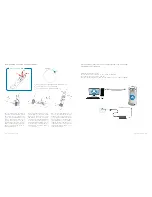
CONFIGURING THE GPS INPUT STREAM AND GPS PARAMETERS
Click
OK
to validate and save your choices.
Activate the GPS (i.e., take into account the GPS data into the ROVINS Kalman
filter):
In EXTERNAL SENSORS area (that is the detailed status pop-up in the
CONTROl page), set the activation parameter of the GPS to ON position by clic-
king on OFF button.
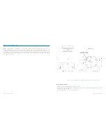
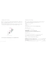
Define the GPS lever arms:
•
LV1 is the signed distance from the ROVINS center of measurements to the GPS
along axis 1 of the illustration
•
LV2 is the signed distance from the ROVINS center of measurements to the GPS
along axis 2 of the illustration
•
LV3 is the signed distance from the ROVINS center of measurements to the GPS
along axis 3 of the illustration
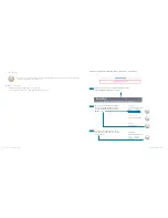
Step 5:
Step 6:
Step 4:
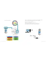
Choose
INPUTS
under
INSTALLATION
Menu
Associate
GPS
to
INPUT A
by clicking in the intersec-
tion of the
INPUT A
column and
GPS
row
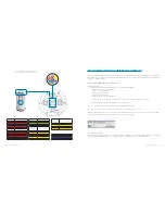
Configure the relevant parameters of the
INPUT A
by
choosing them in the various drop-down lists of the
Protocol, Physical Link, Serial and/or Ethernet areas.
Step 2:
Step 3:
Step 1:


