
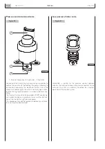


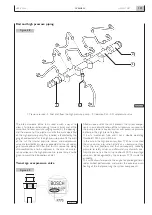


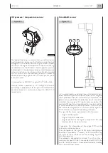


Oil pressure / temperature sensor
The body of the sensor is similar to that one of the air pres-
sure/temperature sensor and the functions carried out are
analogous. It is assembled onto the engine oil filter support,
to measure the engine oil temperature and pressure.The sig-
nal detected is sent to ECU EDC that manages low pressure
indicator light. In this appliance, pressure and oil temperature
values are not shown by instruments but the data are used
by ECU to carry out the monitoring functions. In order to
control oil pressure gauge on the instrument panel, a specif-
ic sensor is used.
It is connected to ECU EDC by pins A9, A19, A33 e A35
Pressure sensor is powered by a 5 V voltage and the out-
put voltage is proportional to the pressure detected. Tem-
perature sensor has a resistance of about 2.5 k
Ω
at 20 °C
temperature.
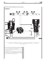
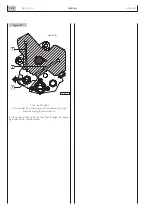
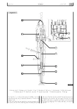
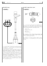
Crankshaft sensor
It is a variable reluctance inductive type, which generates peri-
odical alternate signal due to flow variation in the magnetic
circuit produced inside the cranckshaft by the presence of a
permanent magnet. It faces the pulley keyed on the crankshaft
to detect the passage of 58 tooths every revolution. The
number of 58 tooths has been derived by a constant pitch of
6° which would lead to a total of 60 tooths, 2 of which have
been eliminated to generate an asimmetry of the signal that
ECU EDC uses as crankshaft positioning reference.
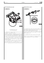
The signal of this sensor is processed in ECU to assess:
-
Engine rotation speed
-
Engine crankshaft acceleration.
-
Angular position of the engine in respect to TDC (top
dead center) of the pair of pistons
It originates the information of the engine RPM on the
instrument and control panel.
The interruption of the signal of this sensor during engine
operation is provided by a “recovery” of ECU actuated using
the signal of the camshaft sensor, thus enabling engine to
carry on operating.
The solenoid is connected to terminal 1 and 2 and has a
resistance of about 900
Ω
. It is connected to ECU EDC by
pins A24 e A25.Terminal 3 is connected to electric shielding
and is insulated from sensor.
N60 ENT M37
OVERVIEW
1.45
APRIL 2004
04_062_N
Figure 56
04_063_N
1
2
3
Figure 57
Содержание N60 ENT M37
Страница 1: ...NEF ENGINE N60 ENT M37 TECHNICAL AND REPAIR MANUAL T E C H N O L O G I C A L E X C E L L E N C E ...
Страница 4: ...N60 ENT M37 IV APRIL 2004 ...
Страница 52: ...N60 ENT M37 OVERVIEW 1 52 APRIL 2004 ...
Страница 54: ...N60 ENT M37 TECHNICAL DATA 2 54 APRIL 2004 ...
Страница 60: ...N60 ENT M37 TECHNICAL DATA 2 60 APRIL 2004 ...
Страница 62: ...N60 ENT M37 ELECTRICAL EQUIPMENT 3 62 APRIL 2004 ...
Страница 92: ...N60 ENT M37 DIAGNOSTICS 4 92 APRIL 2004 ...
Страница 116: ...N60 ENT M37 DIAGNOSTICS 4 116 APRIL 2004 ...
Страница 118: ...N60 ENT M37 MAINTENANCE 5 118 APRIL 2004 ...
Страница 122: ...N60 ENT M37 MAINTENANCE 5 122 APRIL 2004 ...
Страница 124: ...N60 ENT M37 SERVICING OPERATIONS ON INSTALLED ENGINE 6 124 APRIL 2004 ...
Страница 139: ...SECTION 7 TOOLS Page TOOLS 141 N60 ENT M37 TOOLS 7 139 APRIL 2004 ...
Страница 140: ...N60 ENT M37 TOOLS 7 140 APRIL 2004 ...
Страница 146: ...N60 ENT M37 TOOLS 7 146 APRIL 2004 ...
Страница 156: ...APRIL 2004 OVERHAUL 8 156 N60 ENT M37 ...
Страница 164: ...APRIL 2004 OVERHAUL 8 164 N60 ENT M37 ...
Страница 181: ...OVERHAUL APRIL 2004 N60 ENT M37 8 181 ...
Страница 188: ...N60 ENT M37 OVERHAUL 8 188 APRIL 2004 ...
Страница 190: ...N60 ENT M37 SAFETY PRESCRIPTIONS 9 190 APRIL 2004 ...
Страница 193: ......