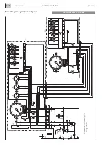

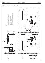


N60 ENT M37
DIAGNOSTICS
4.102
APRIL 2004
GUIDE
T
O
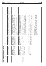
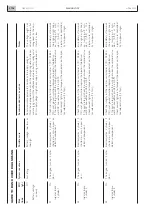
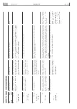
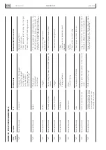
BLINK CODE DIA
GNOSING
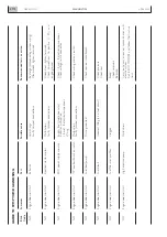
1.1
On
Unbalanced
input
anomal
y
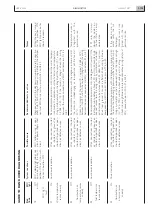
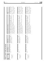
1.4
On
Throttle
position
sensor
anomal
y
EDC
indicator
light
on
for
no
reason
Po
w
er
reduction.
Fast
idling
to
750
RPM
with
the
throttle
lev
er
in
an
y
posi-
tion
Po
w
er
reduction.
With
the
throttle
lev
er
at
rest,
the
engine
runs
at
fast
idling
speed
(750
RPM).
On
mo
ving
the
lev
er
,
the
engine
speed
increases
pro-
gressiv
el
y
to
>
2000
RPM
Po
w
er
reduction.
Fast
idling
to
750
RPM
with
the
throttle
lev
er
in
an
y
posi-
tion
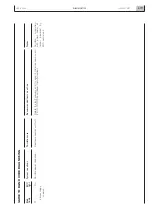
The
resistiv
e
load
sim
ulator
is
not
detected
Idling
switch
(in
throttle
sen-
sor)
signal
shor
ted
or
shor
t-
ed
to
ground
or
shor
ted
positiv
e
or
open
circuit
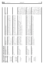
No
throttle
potentiometer
signal.
Shor
ted
or
shor
ted
ground
or
shor
ted
to
positiv
e
or
open
circuit
or
def
ectiv
e
potentiometer
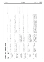
Throttle:
implausib
le
signal
betw
een
the
idling
switch
(saf
ety
contact)
and
the
potentiometer
or
throttle
potentiometer
disconnected
Check
the
integr
ity
of
the
3.3
k
Ω
resistance
betw
een
pins
A2-56
and
A2-74
of
the
EDC
connector
and
the
associated
wir
ing
Read
measur
ab
le
par
ameter
s
with
the
diagnosis
instr
ument
to
ve
rify
the
idling
switch
does
not
w
o
rk
(switching
ON-OFF).
Using
a
m
ultimeter
on
the
component,
check
the
integr
ity
of
the
idling
switch
(switching
ON-OFF).
If
the
switch
is
integr
al,
search
for
a
break
in
the
wir
ing
betw
een
the
throttle
connector
(wir
ing
side)
and
the
EDC
connector
pin
A2-19
e
A2-72
Read
measur
ab
le
par
ameter
s
with
the
diagnosis
instr
ument
to
ve
rify
the
potentiometer
does
not
w
o
rk
proper
ly
(signal
doesn't
change
betw
een
0%
and
100%).
Use
a
m
ultimeter
to
check
the
integr
ity
of
the
potentiometer
(R.total
=
appro
x.
1
k
Ω
).
Check
the
linear
change
in
resistance
of
the
potentiometer
betw
een
the
minim
um
and
maxim
um.
If
the
potentiometer
is
integr
al,
check
the
wir
ing
betw
een
poten-
tiometer connector (wir
ing side) and EDC connector
A2-55,
A2-
81
e
A2-83
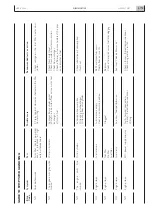
Read
par
ameter
s
with
the
diagnosis
instr
ument
to
identify
the
def
ectiv
e
par
t
of
the
throttle
(potentiometer
or
idling
switch).
a)
Using
a
m
ultimeter
on
the
component,
check
the
integr
ity
of
the
idling
switch
(switching
ON-OFF).
If
the
switch
is
integr
al,
search
for
a
break
in
the
wir
ing
betw
een
the
throttle
connector
(wir
ing
side)
and
the
EDC
connector
pin
A2-19
e
A2-72.
b)
Use
a
m
ultimeter
directl
y
on
the
component
to
check
the
integr
ity
of
the
potentiometer
.
If
the
potentiometer
is
integr
al,
check
the
wir
ing
betw
een
the
potentiometer
and
the
EDC
connector
pin
A2-55,
A2-81
and
A2-83
A
resistiv
e
load
replaces
a
signal
that
is
not
used
in
this
application
Blink
EDC
Code
light
System r
eactions
P
ossible cause
Recommended tests or action
Notes
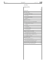
Содержание N60 ENT M37
Страница 1: ...NEF ENGINE N60 ENT M37 TECHNICAL AND REPAIR MANUAL T E C H N O L O G I C A L E X C E L L E N C E ...
Страница 4: ...N60 ENT M37 IV APRIL 2004 ...
Страница 52: ...N60 ENT M37 OVERVIEW 1 52 APRIL 2004 ...
Страница 54: ...N60 ENT M37 TECHNICAL DATA 2 54 APRIL 2004 ...
Страница 60: ...N60 ENT M37 TECHNICAL DATA 2 60 APRIL 2004 ...
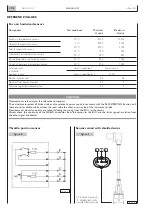
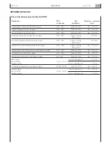
Страница 62: ...N60 ENT M37 ELECTRICAL EQUIPMENT 3 62 APRIL 2004 ...
Страница 92: ...N60 ENT M37 DIAGNOSTICS 4 92 APRIL 2004 ...
Страница 116: ...N60 ENT M37 DIAGNOSTICS 4 116 APRIL 2004 ...
Страница 118: ...N60 ENT M37 MAINTENANCE 5 118 APRIL 2004 ...
Страница 122: ...N60 ENT M37 MAINTENANCE 5 122 APRIL 2004 ...
Страница 124: ...N60 ENT M37 SERVICING OPERATIONS ON INSTALLED ENGINE 6 124 APRIL 2004 ...
Страница 139: ...SECTION 7 TOOLS Page TOOLS 141 N60 ENT M37 TOOLS 7 139 APRIL 2004 ...
Страница 140: ...N60 ENT M37 TOOLS 7 140 APRIL 2004 ...
Страница 146: ...N60 ENT M37 TOOLS 7 146 APRIL 2004 ...
Страница 156: ...APRIL 2004 OVERHAUL 8 156 N60 ENT M37 ...
Страница 164: ...APRIL 2004 OVERHAUL 8 164 N60 ENT M37 ...
Страница 181: ...OVERHAUL APRIL 2004 N60 ENT M37 8 181 ...
Страница 188: ...N60 ENT M37 OVERHAUL 8 188 APRIL 2004 ...
Страница 190: ...N60 ENT M37 SAFETY PRESCRIPTIONS 9 190 APRIL 2004 ...
Страница 193: ......