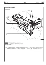
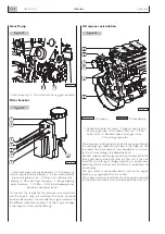


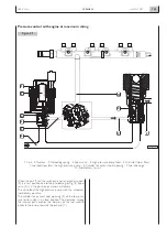


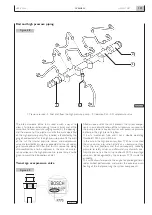


The heart of the system is made up by the solenoid valve
control (19) and by the high pressure radial pump (1). Low
pressure fuel supply takes place by means of a gear pump
(15).While the engine rotates the pump draws fuel from the
tank (9) through the pre-filter (12) and sends it through the
main filter (3) to the limiting valve (18) that sets up the pres-
sure at 5 bar, recirculating the excess delivery to the inlet of
the supply pump (19). The fuel at constant pressure supply
the internal duct for the lubrication of the radial pump (1)
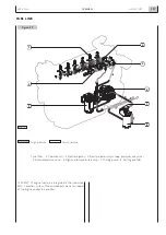
and the inlet of the control solenoid valve. The electrovalve
actuated by the EDC central unit by means of a fast
sequence of pulses, modulates the fuel flow going into the
radial pump and as a consequence the flow and the value of
the high pressure at the outlet of the pump and supplied to
the rail (6). The rail has both the function to store pressure,
timing fuel to the electro-injectors (4) and to support and
connect both to the overpressure valve (7) and the sensor
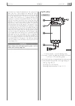
of the internal pressure (5).The rail internal pressure sensor
(5), enables EDC central unit to measure its value and to
control in loop the control solenoid valve in order to always
obtain the high pressure value required by the injection map-
ping, while the overpressure valve,in the event of an anom-
aly on the control system, protects the hydraulic system
components limiting the pressure in the rail at the value of
1750 bar.
The electroinjectors supplied by the exact injection pressure,
by means of an electric control on behalf of the central unit,
inject, when an electromagnetic actuator present in them
N60 ENT M37
OVERVIEW
1.28
APRIL 2004
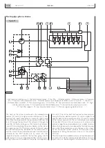
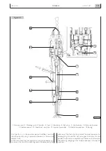
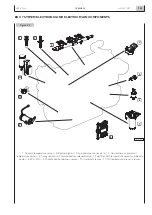
Figure 33
Fuel supply system scheme
1. High pressure radial pump - 2. Fuel temperature sensor - 3. Fuel filter - 4. Electro-injector - 5. Pressure sensor - 6. Common
rail - 7. Common rail overpressure valve - 8. Electro-injector return loop pressurization valve, 1.3 to 2 bar - 9. Fuel tank -
10. Recirculation manifold - 11. Manual priming pump - 12. Pre-filter - 13. Low pressure pump recirculation valve - 14. High
and low pressure pump - 15. Low pressure mechanical feed pump - 16. Low pressure pump by-pass valve -
17. Fuel filter support - 18. Low pressure limiter valve - 19. Pressure regulating electrical valve.
04_040_N
1
17
19
16
18
15
13
14
12
11
10
9
2
3
5
6
7
4
8
Содержание N60 ENT M37
Страница 1: ...NEF ENGINE N60 ENT M37 TECHNICAL AND REPAIR MANUAL T E C H N O L O G I C A L E X C E L L E N C E ...
Страница 4: ...N60 ENT M37 IV APRIL 2004 ...
Страница 52: ...N60 ENT M37 OVERVIEW 1 52 APRIL 2004 ...
Страница 54: ...N60 ENT M37 TECHNICAL DATA 2 54 APRIL 2004 ...
Страница 60: ...N60 ENT M37 TECHNICAL DATA 2 60 APRIL 2004 ...
Страница 62: ...N60 ENT M37 ELECTRICAL EQUIPMENT 3 62 APRIL 2004 ...
Страница 92: ...N60 ENT M37 DIAGNOSTICS 4 92 APRIL 2004 ...
Страница 116: ...N60 ENT M37 DIAGNOSTICS 4 116 APRIL 2004 ...
Страница 118: ...N60 ENT M37 MAINTENANCE 5 118 APRIL 2004 ...
Страница 122: ...N60 ENT M37 MAINTENANCE 5 122 APRIL 2004 ...
Страница 124: ...N60 ENT M37 SERVICING OPERATIONS ON INSTALLED ENGINE 6 124 APRIL 2004 ...
Страница 139: ...SECTION 7 TOOLS Page TOOLS 141 N60 ENT M37 TOOLS 7 139 APRIL 2004 ...
Страница 140: ...N60 ENT M37 TOOLS 7 140 APRIL 2004 ...
Страница 146: ...N60 ENT M37 TOOLS 7 146 APRIL 2004 ...
Страница 156: ...APRIL 2004 OVERHAUL 8 156 N60 ENT M37 ...
Страница 164: ...APRIL 2004 OVERHAUL 8 164 N60 ENT M37 ...
Страница 181: ...OVERHAUL APRIL 2004 N60 ENT M37 8 181 ...
Страница 188: ...N60 ENT M37 OVERHAUL 8 188 APRIL 2004 ...
Страница 190: ...N60 ENT M37 SAFETY PRESCRIPTIONS 9 190 APRIL 2004 ...
Страница 193: ......