


7
b.
Electrical Conduit Connection
• Connect electric conduit to flow switch electrical enclosure.
• Follow accepted electrical practices when installing fittings
and making connections.
• Refer to and follow local codes and standards when
selecting the types of electrical fittings and conduit to
connect to flow switch.
c.
Determine which switch action is required for the
flow switch.
• “Flow” means that the switch will close circuit
C.-N.O. and open circuit C.-N.C. when flow rate
is increased above setpoint of flow switch.
• “No Flow” means that the switch will open circuit
C.-N.O. and close circuit C.-N.C. when flow rate
is decreased below setpoint of flow switch.
d.
Based upon the mode of operation (“Flow” or “No-
Flow”) required, complete the appropriate steps to
connect wires to flow switch. Use a Phillip’s head
screwdriver to loosen and tighten switch terminal
screws when attaching wires.
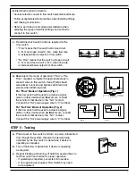
For “Flow” Mode of Operation (Fig. 1)
If the flow switch will be used to actuate a signal,
alarm or other device when
flow
occurs, connect
the wire from that device to the “N.O.” contact.
Connect the “Hot” power supply wire to “C” terminal.
For “No Flow” Mode of Operation (Fig. 2)
If the flow switch will be used to actuate a signal,
alarm or other device when
no flow
occurs, connect
the wire from that device to the “N.C.” contact.
Connect the “Hot” power supply wire to “C” terminal.
COMMON
NORMALLY
OPEN
NORMALLY
CLOSED
Flow
Opens
Circuit
Normally
closed
3
Common
1
Flow
Closes
Circuit
2
(
(
Normally
open
(
(
Common
(
(
FS8-W
LINE
LOAD
Fig. 1
HOT
3
1
2
FS8-W
LINE
LOAD
Fig. 2
HOT
3
1
2
a.
Place cover on flow switch and turn on power. Initiate fluid
flow through the system. Observe the device being
activated by the flow switch to determine if device is
operating as required.
b.
Turn off fluid flow to determine if device is operating
as required.
c.
Repeat initiating and turning off fluid flow several times to
test flow switch and device for proper operation.
- If operating as required, put system into service.
- If not operating as required, Flow Switch may need
to be adjusted.
OFF
ON
STEP 5 - Testing
C.
N.O.
FLOW
N.C.
C.
N.O.
NO FLOW
N.C.