


3
NOTE: DO NOT USE LIQUID FLOW SWITCHES ON SYSTEMS
WITH FLOW VELOCITY GREATER THAN 10 FEET
(3M) PER SECOND.
Pipe
Mode of Operation
Size NPT
Flow
Velocity
No Flow
Velocity
in. (mm) Settings
gpm (lpm) fps (mps) gpm (lpm) fps (mps)
Factory or
1 (25)
Minimum
4.9 (18.5) 1.82 (.55) 3.4 (12.9) 1.25 (.38)
27
Maximum 17.6 (66.6) 6.53 (2.60) 15 (56.8) 5.56 (1.69)
(102)
Factory or
1
1
⁄
4
(32)
Minimum
7.5 (28.4) 1.60 (.49) 5.3 (20.1) 1.14 (.35)
47
Maximum 29
(110) 6.23 (1.9) 24.6 (93.1) 5.28 (1.61)
(178)
Factory or
1
1
⁄
2
(40)
Minimum
9.4 (35.6) 1.48 (.45) 6.7 (25.4) 1.05 (.32)
63
Maximum 37.8 (143) 5.95 (1.81) 32.2 (122) 5.07 (1.54)
(239)
Factory or
2 (50)
Minimum
13.7 (51.8) 1.31
(.4) 9.4 (35.6) .9
(.27)
105
Maximum 56.4 (214) 5.39 (1.64) 47.4 (179) 4.53 (1.38)
(398)
Factory or
2
1
⁄
2
(65)
Minimum
17.9 (67.8) 1.20 (.36) 12.1 (45.8) .81
(.25)
149
Maximum 71.3 (270) 4.78 (1.46) 59.2 (224) 3.97 (1.21)
(565)
Factory or
3 (80)
Minimum
24.2 (91.6) 1.05 (.32) 16.4 (62.1) .71
(.22)
230
Maximum 89
(337) 3.87 (1.18) 72.5 (274) 3.15 (.96)
(872)
Factory or
4 (100)
Minimum
35.3 (134) .89
(.27) 27
(102) .68
(.21)
397
Maximum 118 (446) 2.89 (.91) 105 (397) 2.64
(.8)
(1505)
Factory or
5 (125)
Minimum
48.6 (184) .78
(.24) 37.4 (142) .6
(.18)
654
Maximum 178 (674) 2.86 (.87) 160 (606) 2.57 (.78)
(2479)
Factory or
6 (150)
Minimum
60.3 (228) .67
(.20) 46.8 (177) .52
(.16)
900
Maximum 245 (927) 2.72 (.83) 225 (852) 2.5
(.76)
(3411)
Values are ± 10%
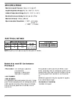
Max. Flow
Rate gpm
(lpm) w/o
Paddle Damage
FLOW RATES
Flow rates required to activate flow switch are shown
in chart below. The values are calculated for sensing
water (potable, non-polluted) in a horizontal pipe.
Settings will vary when used to sense flow of other
fluids or if located in a vertical pipe.