CGW-I Cellular Gateway BRI-GSM : Installation and Operation Manual
14
o
Connect the RS-232 cable from a PC to the RS-232 interface of the
CGW-I.
Note:
Communication with the CGW-I can be done over either the RS-232 interface or LAN
connection. Even you plan to communicate with the CGW-I over a LAN, you must
first connect the RS-232 cable to define the network parameters and complete the
initial setup
p
Connect the RJ-45 cable from the PBX to the ISDN interface of the
CGW-I.
q
If you need to synchronize the CGW-I time clock, connect the RJ-45 cable
from the NT interface to the Synch-In interface of the CGW-I.
r
Connect the supplied 9VDC 1.5A power converter cable to the CGW-I
power supply connector.
If you want to communicate over a LAN, once you have completed steps 1-5
you must remove the RS-232 cable and connect an RJ-45 Cable from your
LAN to the LAN interface of the CGW-I.
Turning on Your CGW-I
CAUTION:
To avoid damage to your CGW-I device, the 9V adapter should be disconnected from the
electric power-outlet when inserting or removing the SIM card.
After you connect the supplied 9VDC power supply converter cable into the
9VDC port of the CGW-I device plug it into the appropriate power supply. A
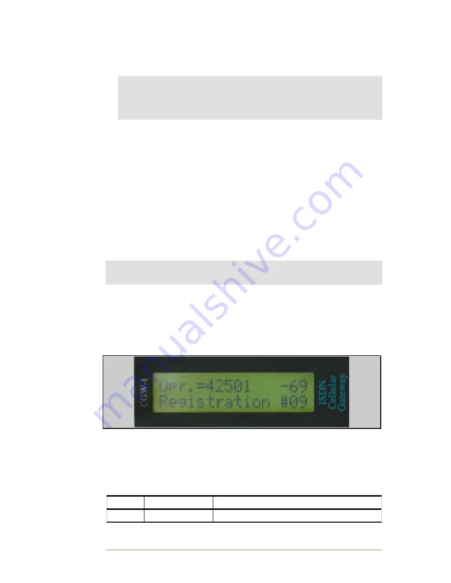
message should now appear on your CGW-I LCD, indicating that the device
is now working. For a description of the different messages, please see LCD
Messages on page 15.
You are now ready to configure your new CGW-I device.
2.6.
LED Indicators
Your device contains 4 LEDs that indicate the status of communications
going through the device. The following table describes the LEDs and their
purpose.
Name LED
Status
Li
On
LAN cable is connected to CGW-I


