6
On longer stretches, when the support profiles have already been installed
or are being held in a vice and the Shaft-Clamp Profile has been pressed into
place, you can press the shaft into the Shaft-Clamp Profile section by section
using the Mounting Aid (0.0.265.38) and a lever in the form of a suitable
round steel bar.
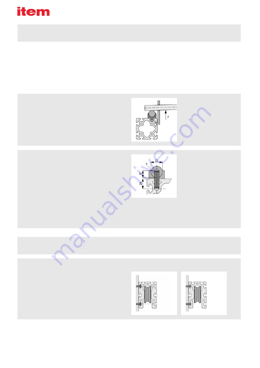
d = ⌀ 10 mm
b = DIN 6325-10x40 dowel pin
When higher loads are involved, it is advisable to secure the Shaft. Ideally, a
Combination Drilling Jig (c) should be used to machine the Shaft, Shaft-Clamp
Profile and Support Profile as detailed in the following steps:
▪
Using a carbide drill, cut a blind hole in the Shaft, 40 mm from the end face
(as shown in the drawing)
▪
At the same distance from the end face, cut a through hole (d) through the
Shaft-Clamp Profile and Support Profile together, up to the centre bore of
the Support Profile
▪
Press dowel pin (b) DIN 6325 into the Shaft
▪
Install the Shaft into the Shaft-Clamp Profile as described above
Installation
Shaft-Clamp Profile and Shaft:
There are various methods for assembling support profile, Shaft-Clamp Profile
and Shaft.
To make installation easier, apply a film of oil or grease to the outer surfaces of
the Shaft-Clamp Profile that come into contact with the support profile before
pressing it into the groove. Do the same to the contact points between the
Shaft and Shaft-Clamp Profile and to the guiding Shaft itself. When working
with short support profiles that have not yet been connected to a fixture, it is
advantageous to undertake installation in the following steps:
▪
Press the Shaft-Clamp Profile into the relevant groove of the support profile
▪
Use a vice (fitted with protective jaw plates) to press in the Shaft
▪
Follow the same sequence for the other side
Bearing Units can be mounted onto any MB system profile element. There
are two different methods that can be used to secure Bearing Units to the
standard Line 8 groove:
a) The heads of the Button-Head Screws and Washers are located within
one of the grooves on the Bearing Unit, which means through holes need to
be provided so that an Allen key can reach the screws. Holes for the most
common fixing arrangement have been pre-drilled into the Bearing Units. For
other fixing arrangements, such as turned through 90° and using the second
groove, holes will need to be drilled.
b) The T-Slot Nuts are located within one of the grooves on the Bearing Unit
and the fastening screws are inserted into the guide carriage.
Guide carriage/Bearing Units
c = Art. No. 0.0.373.15 for Shaft D25


