7
1.
2.
3.
On longer stretches, when the support profiles have already been installed
or are being held in a vice and the Shaft-Clamp Profile has been pressed into
place, you can press the shaft into the Shaft-Clamp Profile section by section
using the Mounting Aid (0.0.265.38) and a lever in the form of a suitable
round steel bar.
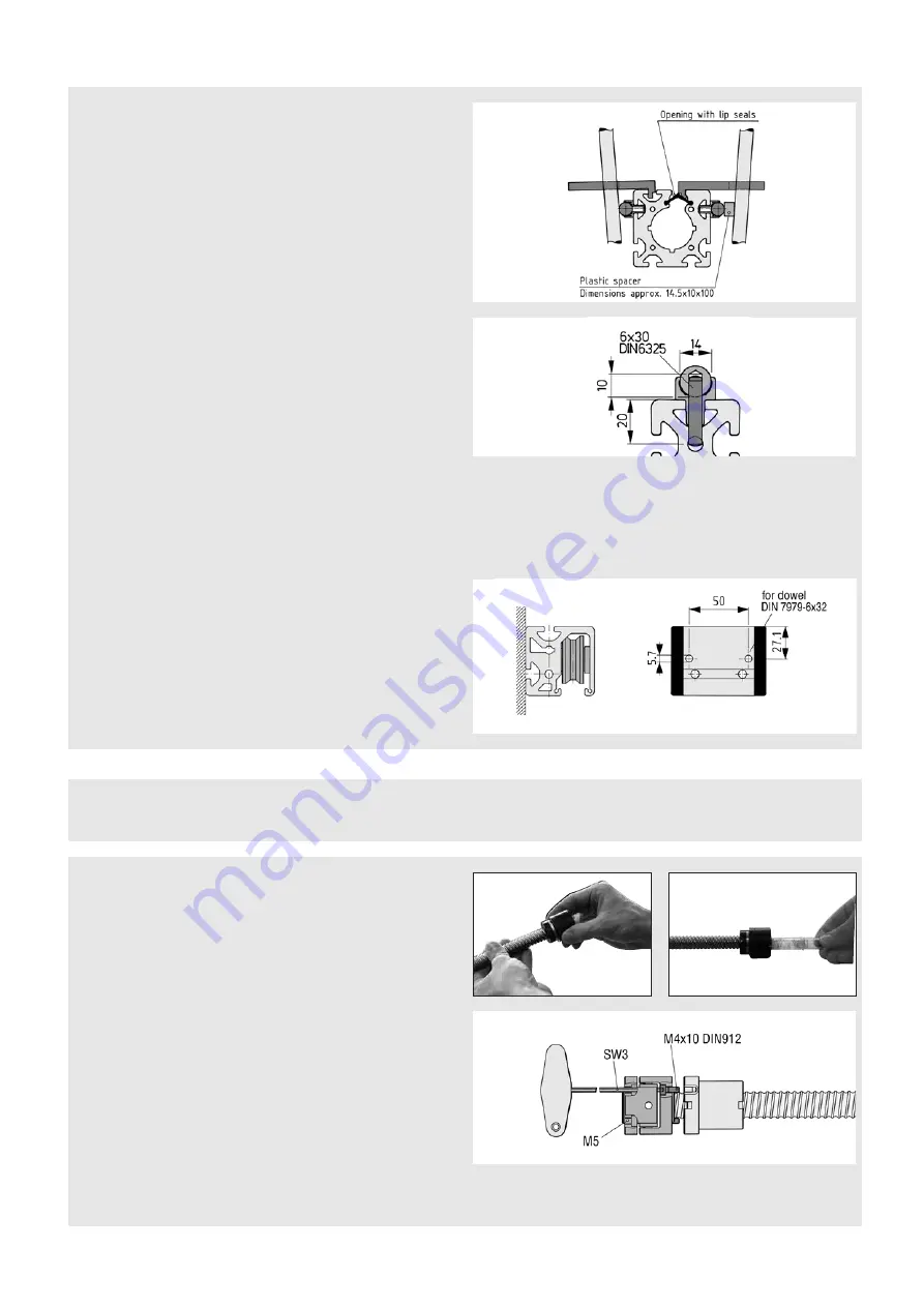
a = DIN 7979-6x32 dowel pin
If there are undefined loads on the guide unit such as impact loads that
could cause movement in the Bearing Units, the Bearing Units will need to be
reinforced. You can do this by drilling and pinning (a) the Units in the positions
indicated or the areas shown in dark grey.
When higher loads are involved, it is advisable to secure the Shaft. Ideally, a
Combination Drilling Jig (c) should be used to machine the Shaft, Shaft-Clamp
Profile and Support Profile as detailed in the following steps:
▪
Using a carbide drill, cut a blind hole in the Shaft, 40 mm from the end face
(as shown in the drawing)
▪
At the same distance from the end face, cut a through hole (d) through the
Shaft-Clamp Profile and Support Profile together, up to the centre bore of
the Support Profile
▪
Press dowel pin (b) DIN 6325 into the Shaft
▪
Install the Shaft into the Shaft-Clamp Profile as described above
b = DIN 6325-6x30 dowel pin
c = Order No. 0.0.373.55 for Shaft D14
d = ⌀6 mm
Shaft-Clamp Profile and Shaft D14:
There are various methods for assembling support profile, Shaft-Clamp Profile
and Shaft.
To make assembly easier, apply a film of oil or grease to the outer surfaces of
the Shaft-Clamp Profile that come into contact with the support profile before
pressing it into the groove. Do the same to the contact points between the
Shaft and Shaft-Clamp Profile and to the guiding Shaft itself. When working
with short support profiles that have not yet been connected to a fixture, it is
advantageous to undertake installation in the following steps:
▪
Press the Shaft-Clamp Profile into the relevant groove of the support profile
▪
Use a vice (fitted with protective jaw plates) to press in the Shaft
▪
Follow the same sequence for the other side
Installing the Linear Unit
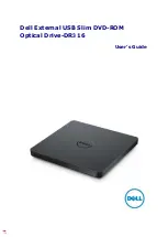
1. Cut the screw to length and deburr it. When screwing on the drive nut, take
extra care to ensure the balls do not fall out.
Do not pull the assembly tube out of the drive nut under any circumstances!
2. With the assembly tube still fitted, place the drive nut against the end-face
of a free end of the screw and carefully turn it onto the screw (right-hand
thread).
The assembly tube will be pushed slowly out of the nut insert as you do this.
Keep the tube to use when disassembling the system.
3. If balls escape despite taking great care during installation, individual balls
can be reinserted. To do this, carefully turn the drive nut up to the free end
of the screw until you can see individual balls. You can then insert the es-
caped balls between balls that are still in the raceway (never into the return
system). Do not use drive nuts that contain an insufficient number of balls in
ball screw units (high noise, service life).
Once you have installed the drive nut, you can slide on the gimbal adapter
(on the flange side of the drive nut) and screw it to the drive nut. To do this,
carefully turn the unit until it is approx. 20 mm from the end of the screw.
Note:
To prevent backlash in the drive train, the gimbal adapter is stiff to move.


