background image

30

SLS/SLH 10/06

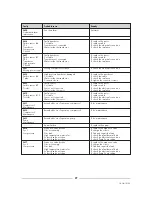
Index Meaning

Read/Write

Level

gsegna

1

System #1 state

Read

1

0 =

Off

System #1 state

1 =

Pumpdown

System #1 state

2 =

Comp run

System #1 state

3 =

Sys alarm

2

System #2 state

Read

1

as per sys 1

3

Unit state

Read

1

0 =

on

Unit state

1 =

off by alarm

Unit state

2 =

off by supervisor

Unit state

3 =

off by low OAT

Unit state

4 =

off by remote

Unit state

5 =

off

7

RWT/LWT temperature control

Read/Write

2

0= RWT

13

Pump stand-by time

Read/Write

2

01– 24 hr

14

Pump power off delay

Read/Write

2

00 – 60 sec

15

Pump down max time

Read/Write

2

5– 90 sec

25

Night mode start hour (PM)

Read/Write

2

00 – 12

26

Night mode start minutes

Read/Write

2

00 – 59

27

Night mode end hour  (AM)

Read/Write

2

00 – 12

28

Night mode end minutes

Read/Write

2

00 – 59

Содержание SLS-SLH

Страница 1: ...Chiller unit SLS SLH...

Страница 2: ...nect the Chiller Control to a BMS network Remote Display Terminal Wire Remote Control Phase monitor kit 2 CONTROL OF SLS SLH WITH 2 SCREW COMPRESSORS The SLS SLH machines with 2 screw compressors are...

Страница 3: ...s you to set the control parame ters values and to move from one mask to another not backlighted 4 Arrow down key allows you to set the control para meters values and to move from one mask to another...

Страница 4: ...essor Off Run Off Run Run Man NO AL17 Sys 2 pressure diff compressor Run Off Run Off Run Man NO AL18 Failure of clock card Run Run Run Run Run Man NO AL19 AL21 B1 Tin Sensor failure Off Off Off Off Ru...

Страница 5: ...Com pr es s or 000000 h SYS 2 Com pr es s or 000000 h I nser tt he passw or d 0000 1234 O f f setpr obes T i n C 9 9 9 9 0 SP 1 bar 9 9 9 9 0 DP 1 bar 3 9 9 0 T ai r C 9 9 9 9 0 T out C 9 9 9 9 0 SP...

Страница 6: ...river 2 status U No anomaly N 2 3 5 PRINTING KEY Not used 2 3 6 I O INPUT OUTPUT KEY Press the I O key to access the display masks of the values of all sensors mounted on the machine Acronym Descripti...

Страница 7: ...TO CIRCUITO 1 U Storico driver 1 SH 00 0 Steps 0000 Temp 00 0 Press 00 0 POSITION AND TERMODINAMIC PARAMETER FROZEN WHEN THE ALARM HAPPENED ON CIRCUIT 2 POSIZIONE E GRANDEZZE TERMODINAMICHE CONGELATE...

Страница 8: ...point see Service level When the machine is turned on every single circuit is activated through the SYSTEM ON OFF parameters SET key 2 3 9 SERVICE LEVEL KEY Press the Prog key correct password 1234 to...

Страница 9: ...illerNet Flag N NO Y YES N Water temperature RWT P Type control Flag RWT P I LWT RWT P RWT P I Sec 0 999 600 Min time on compressor Sec 0 999 300 Min time off compressor Sec 0 999 300 Loading time com...

Страница 10: ...x LWT Limit C 20 55 47 Diff C 0 5 10 3 Interlock enabled Flag N NO Y YES N Phase control alarm enabled Flag N NO Y YES N Delay time flowswitch alarm running 1 20 1 start up Sec 1 20 5 LOP Se point bar...

Страница 11: ...only if the speed controller is available otherwise set it to STEP SETTING OF EEV EX7 or EX8 type for YSLS R134a SERVICE LEVEL 1234 GO INTO THE SERVICE LEVEL PROG 1234 SCROLL THE MASKS DOWN TO THE NEX...

Страница 12: ...Banda morta 0 0 C m_manuf_d1_ch2 m_manuf_d2_ch2 m_manuf_d1_ch3 increase this value if the SH is not controlled 15sec with plate heat exchanger normal range between 2 4 C normal range between 1 10 If...

Страница 13: ...03 0 C Tempo int 002s Param COMM CH U LOP protection LOP threshold 3 0 C Int time 001s Param COMM CH U MOP threshold 12 0 C Int time 010s Delay start up 060s Param COMM CH U High TCond protection TCo...

Страница 14: ...B8 N For standard B8 Y For master unit B1 Y B2 Y B3 Y Note B9 N For chiller B9 Y For heat pump B4 Y B5 Y B6 Y B7 Y B10 N For chiller B10 Y For heat pump B8 N B9 N B10 N See note Transducer Suction pr...

Страница 15: ...rel 2 flag N NO Y YES Y Logica rel 3 flag N NO Y YES N Gradino 3 75 Logica rel 1 flag N NO Y YES N Logica rel 2 flag N NO Y YES N Logica rel 3 flag N NO Y YES Y Gradino 4 100 Logica rel 1 flag N NO Y...

Страница 16: ...off Until the LWT is below the Setpoint com pressors are unloaded according to the Unload time parameter value 4 COMPRESSORS LEAVING LIQUID CONTROL HEATING MODE If leaving Control mode is selected th...

Страница 17: ...higher is the RWT the more stages will be loaded according to the compressor activity logic timer and rules described For each stages will be respected the minimum time ON the minimum time OFF and lo...

Страница 18: ...r the fans will start Below is a chart showing the correlation Table 1 Startup Fan Values There is one high pressure transducer each system If only one compressor is running the fans control to its di...

Страница 19: ...HP1 LS Diff The fans start under sensor air B4 control OAT During the fans running If DP HP1 one step is load independent by OAT value If DP LP1 unloaded the step DP is the leader between the two tra...

Страница 20: ...ing rule If Tair Low Air Temp Heating then AO Max Fan Speed If Low Air Temp Cooling Tair High Air Temp Cooling then AO from Max to Min with linear progression If Tair High Air Temp Heating then AO Min...

Страница 21: ...21 SLS SLH 10 06 10 CONDENSER FAN CONTROL HEATING MODE IN STEP LOW Default 15 C HIGH Default 30 C...

Страница 22: ...lue AO is always between the Min Fan Speed and the Max Fan Speed Whenever one of the two high pressure measures by the transducer reaches the MDP Value soon the fan must run at max speed until that hi...

Страница 23: ...Default must be 12 hours If the pump is not controlled by the electronic control put the stand by value at 00 If the unit is in stand by the pump must anyway be start ed if the Antifreeze heater is po...

Страница 24: ...o set compressor switch off time Reversing Off parameter when system enter and exit from defrost mode Compressors are not switched off if time is set to 0 seconds Moreover cycle reversion dur ing norm...

Страница 25: ...To clean the filter To clean the exchanger To check the plant pressure drop AL09 Thermal switch compressor 1 AL10 Thermal switch compressor 2 AL11 Recovery antifreezing AL12 Thermal switch fans group...

Страница 26: ...cuit 1 AL24 Failure sensor B4 Outdoor air temperature AL25 Failure sensor B 5 Outlet water temperature AL16 Pressure diff compressor SYS 1 No pressure variation Faulty high pressure transducer Faulty...

Страница 27: ...ck the electrical connection Water inside the sensor To check the insulation AL30 Faulty sensor To replace the sensor Failure sensor B 10 Cut cable To replace cable Tr outlet Sensor not connected To c...

Страница 28: ...9 System 1 defrost temp Read 2 50 0 105 0 C 10 System 2 defrost temp Read 2 50 0 105 0 C 11 Regulated temperature RWT or LWT Read 1 50 0 105 0 C 12 Sys 1 Fan speed index Read 2 0 0 10 0 13 Sys 2 Fan s...

Страница 29: ...Read 2 no alarm yes alarm 59 B7 faulty probe Read 2 no alarm yes alarm 60 B8 faulty probe Read 2 no alarm yes alarm 61 B9 faulty probe Read 2 no alarm yes alarm 62 B10 faulty probe Read 2 no alarm yes...

Страница 30: ...e 2 off by supervisor Unit state 3 off by low OAT Unit state 4 off by remote Unit state 5 off 7 RWT LWT temperature control Read Write 2 0 RWT 13 Pump stand by time Read Write 2 01 24 hr 14 Pump power...

Отзывы: