background image


Basic

 operation


Copyright © ITECH Electronics Co., Ltd.


21 

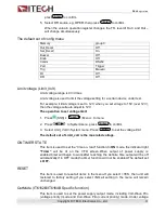
PORT mode 

A 4-pin connector in the rear panel is provided for digital input and output signals. 


This  digital  port  can  be  configured  to  provide  Fault/Inhibit,  External  Trigger  or 
Digital I/O functions. The signal level is TTL.   

Choose one mode in the menu: 

Trigger: 

select the port mode as trigger, In(+) function as TRIG pin, In(-) function 

as GND


RI/DFI

The Inhibit Input pin can be used to control the output state of the power 

supply (RI function). The Fault Output pin (DFI function) can be used to indicate 
internal faults of the power supply. 

Digital

Digit I/O port, Read and control output and input state of the 2 available 

pins.


The default set is Trigger. 

Mode 

Pin


Trigger 

RI/DFI 

Digital I/O 

In + 

Trigger in   

Inhibit Input   

Digital Input   

In - 

GND 

GND 

GND 

Out + 

No Use 

Fault Output   

Digital Output 

Out - 

No Use 

GND 

GND 


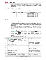
Trigger source (TRIG) 

The  power  supply  supports  4  different  trigger  modes  for  LIST  test.  Manual, 
External,  Bus  and  Immediat.  Configure  one  of  the  trigger  sources  before 
performing trigger operation


Manual

:  When  this  function  is  enabled,  you  can  generate  an  immediate  trigger 

pulse by pressing 

(Shift)+

Enter

Trigger


External: 

External  trigger  signal  (TTL),  you  should  set  PORT  as  Trigger  in  the 

menu at the same time. When this function is enabled, the power supply can be 
triggered with a low TTL pulse applied to pin In + and In 

– (short In + and In –) of 

the terminal connector in the rear. The TTL on pulse width should be at least 5 ms. 

Bus: 

When this function is enabled, you can trigger the power supply by sending a 

TRIgger command to the power supply 

Immediat: 

You can trigger the power supply by sending the command TRIG: IMM 

in any case, regardless of the trigger source selected in the current menu. 

The default set is Manual 

Содержание IT6121B

Страница 1: ...High Speed and High Accuracy Programmable Power Supply Series IT6100B User s Manual Model IT6121B IT6122B IT6123B IT6132B IT6133B IT6162B IT6164B Version V1 1 ...

Страница 2: ... the materials in this document that conflict with these terms the warranty terms in the separate agreement shall prevail Technology Licenses The hardware and or software described herein are furnished under a license and may be used or copied only in accordance with the terms of such license Restricted Rights Legend Restricted permissions of the U S government Permissions for software and technic...

Страница 3: ...ll be on the account of customer Limitation of Warranty This Warranty will be rendered invalid if the product is Damage caused by circuit installed by customer or using customer own products or accessories Modified or repaired by customer without authorization Damage caused by circuit installed by customer or not operating our products under designated environment The product model or serial numbe...

Страница 4: ...of the load power cord must be carry out the full rated short circuit output current of the power securely Ensure the voltage fluctuation of mains supply is less than 10 of the working voltage range in order to reduce risks of fire and electric shock Do not install alternative parts on the instrument or perform any unauthorized modification Do not use the instrument if the detachable cover is remo...

Страница 5: ...ardous or toxic substances are expected to leak or deteriorate during normal use The expected service life of the product is 10 years The product can be used safely during the 10 year Environment Friendly Use Period EFUP Upon expiration of the EFUP the product must be immediately recycled Waste Electrical and Electronic Equipment WEEE Directive 2002 96 EC Waste Electrical and Electronic Equipment ...

Страница 6: ... 4 2 2008 EN 61000 4 2 2009 IEC 61000 4 3 2006 A1 2007 A2 2010 EN 61000 4 3 2006 A1 2008 A2 2010 IEC 61000 4 4 2004 A1 2010 EN 61000 4 4 2004 A1 2010 IEC 61000 4 5 2005 EN 61000 4 5 2006 IEC 61000 4 6 2008 EN 61000 4 6 2009 IEC 61000 4 11 2004 EN 61000 4 11 2004 1 The product is intended for use in non residential non domestic environments Use of the product in residential domestic environments ma...

Страница 7: ...Panel Introduction 8 2 3 Rear Panel Introduction 9 2 4 Keyboard Introduction 11 2 5 Function description of VFD status indicators 12 2 6 Power on self test 12 Chapter3 Basic operation 15 3 1 Local Remote Mode 15 3 2 Setting the Voltage 15 3 3 Setting the Current 16 3 4 On Off Operation 16 3 5 Set mode and Meter mode 17 3 6 CC and CV 17 3 7 Save and recall operation 17 3 8 Trigger operation 18 3 9 ...

Страница 8: ... power cord that matches the specifications of power socket used in the area See the Section Connecting the Power Cord for details USB cable x1 CD x1 It contains IT6100B power supply User s Manual Programming Guide and other user documentations Ex factory Test Report x1 It is the test report of the instrument before delivery NOTE After confirming that package contents are consistent and correct pl...

Страница 9: ...Inspection and Installation Copyright ITECH Electronics Co Ltd 2 IT6121B IT6122B IT6123B IT6132B IT6133B Models Dimension Width 214 5 mm Height 88 2 mm Depth 354 6 mm Detailed Dimension Drawing ...

Страница 10: ...Inspection and Installation Copyright ITECH Electronics Co Ltd 3 IT6162B Model Dimension Width 482 5 mm Height 88 2 mm Depth 650 mm Detailed Dimension Drawing ...

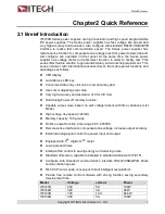
Страница 11: ...can be mounted on a standard 19 rack ITECH provides user with IT E151 rack as a mount kit The detailed operation please refer to the User Manual of your mount kit 1 4 Connecting the Power Cord Connect power cord of standard accessories and ensure that the power supply is under normal power supply AC power input level Working voltage for IT6121B IT6122B IT6123B IT6132B IT6133B IT6162B is 110V ...

Страница 12: ... model fails to meet local voltage requirements please contact distributor or factory for change E N L E L N E N L E L N China IT 171 America Canada Japan IT E172 Europe IT E173 Britain IT E174 IT6162B IT6164B provides the standard power cords as below The power cords supplied with this product is certified for safety In case the supplied lines assembly needs to be replaced or an extension lines m...

Страница 13: ...erminal in the rear panel of the power supply Connect the wire zero line and ground to the corresponding terminal of the device Before inserting please loose the screw lock the screw when it is inserted Connect the three terminals red to line L black to neutral N and yellow to ground G on the other end of the power cord to your AC distribution panel ...

Страница 14: ...iniferous LED key Convenient data entry via knob or numerical key pad Use cursor adjusting step value Very high accuracy and resolution of 0 1mV 0 1mA Hold during Power off memory function Capable output wave based on edit voltage current with time variations List Mode High voltage rise speed 20mS Memory capacity 100 groups On time output function time range 0 01 60000S Remote sense interface to c...

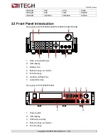
Страница 15: ...t Panel Introduction Front panel of IT6121B IT6122B IT6123B IT6132B IT6133B 1 Shift Local and Power 2 VFD display 3 Rotary knob 4 Numeric keys esc button 5 Function keys 6 up down left right key 7 output terminals Front panel of IT6162B IT6164B 1 Power switch 2 VFD display 3 Shift and Local key 4 Numeric keys esc button 5 Function keys ...

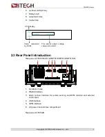
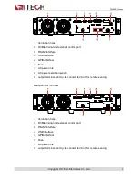
Страница 16: ...of IT6121B IT6122B IT6123B IT6132B IT6133B 1 Ventilation holes 2 RS232 interface 3 Qucik connect terminal for remote sensing and DVM terminal and external control port 4 USB interface 5 GPIB interface 6 AC power inlet and fuse compartment Rear panel of IT6162B OFF 1 000V 1 0000A 0 0001V Value measured by DVM The actual output voltage value and current VFD display ...

Страница 17: ...PIB interface 6 Fuse 7 AC power inlet 8 AC power selection switch 9 output terminals and qucik connect terminal for remote sensing Rear panel of IT6164B 1 Ventilation holes 2 DVM terminal and external control port 3 RS232 interface 4 USB interface 5 GPIB interface 6 Fuse 7 AC power inlet 8 output terminals and qucik connect terminal for remote sensing ...

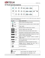
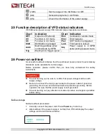
Страница 18: ... Set the current value and enter into the menu Recall Save Recall Save operating data from internal memory Meter Meter DVM Switch between Setting Meter display also used to switch to DVM measuring state Enter Enter Trigger Press to confirm numerical entries or provide a trigger signal On Off Lock Set the output state of the power supply or to lock the front panel keys Right left keys to adjust the...

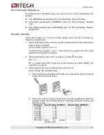
Страница 19: ...ignal 2 6 Power on self test A successful self test indicates that the purchased power product meets delivery standards and is available for normal usage Before operation please confirm that you have fully understood the safety instructions To avoid burning out be sure to confirm that power voltage matches with supply voltage Be sure to connect the main power socket to the power outlet of protecti...

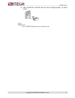
Страница 20: ...ring of power cord 2 Incorrect wiring of power cord Re connect the power cord and check whether the exception is removed 2 Check whether the power in On Power key is under On status Yes 3 No Please check the Power key to start power and check whether the exception is removed 3 Check whether the fuse of power supply is burned out If yes change fuse Detailed steps 1 Pull out power line and take out ...

Страница 21: ...Quick Reference Copyright ITECH Electronics Co Ltd 14 3 After replacement install the fuse box back to original position as shown below NOTE Fuse of IT6162B IT6164B can unscrew directly by hand ...

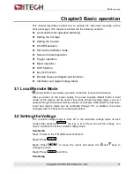
Страница 22: ...o local mode After you power on the power supply the power supply s default mode is local mode all the buttons can be used in this mode While in remote mode you can t operate through front panel directly except Local Meter Shift On Off Lock keys Local and remote mode can be controlled through PC In addition the mode changing will not influence the output parameters 3 2 Setting the Voltage The cons...

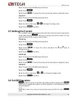
Страница 23: ...t output Solution1 Step1 Power on the IT6100B series instrument Step2 Press I set I set Step2 Press to move the cursor and press the and keys to change the value Step3 Press Enter to confirm Solution2 Step1 Power on the IT6100B series instrument Step2 Press I set I set Step3 Press to move the cursor and turn the knob to change the value Solution3 Step1 Power on the IT6100B series instrument Step2 ...

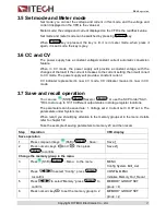
Страница 24: ...epresents it s now CV mode CC indicater means it s now in CC mode 3 7 Save and recall operation You can use Shift Recall Save or Recall or use the SCPI order SAV RCL to store up to 10 10 different output states in storage register locations The parameters can be saved are 1 Voltage set 2 Current set 3 OVP set 4 The parameters under System menu When recall you should pay attention to the memory gro...

Страница 25: ...view the parameters Press ESC to return to the higher level menu and to return to the main operating mode MENU Config CONFIG MENU Initialize Reset config Select whether to reset the config menu No Yes Memory Memory GROUP SET Memory group set for save recall function group 0 0 9 Out_Recal OUT RECALL Set the Power ON OFF state after power up On Remembers and restores the Power ON OFF state of the po...

Страница 26: ...mand RI RI MODE Config RI Remote Inhibit mode Off Disable this function Latching Live DFI DFI SOURCE Config DFI Discrete Fault Indicater mode Off Disable this function QUES Question bit OPER Operation bit ESB Event State bit RQS Require bit System SYSTEM MENU Limit_volt LIMIT VOLTAGE SET Limit 30 10V On_Timer ON TIMER STATE Output timer function state On ON TIMER SET timer 60 000 0 01 60000 0S Off...

Страница 27: ...ing Output voltage and current will always be 1V 0 1A Otherwise the output value will be the same with last power off state The default setting is ON Key sound set Buzzer This item can set the key sound state If in ON mode then when you press a button the power supply will beep If in OFF mode the beeper will not make a sound The default set is in OFF mode Rotary knob set KNOB This item is used to ...

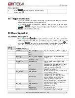
Страница 28: ...In GND GND GND Out No Use Fault Output Digital Output Out No Use GND GND Trigger source TRIG The power supply supports 4 different trigger modes for LIST test Manual External Bus and Immediat Configure one of the trigger sources before performing trigger operation Manual When this function is enabled you can generate an immediate trigger pulse by pressing Shift Enter Trigger External External trig...

Страница 29: ...er supply output is on if the level at the RI port is TTL Low The output of the power supply is off Note when use RI function the PORT item in menu should be selected to RI DFI Discrete Fault Indicator DFI The output level of DFI Out and Out reflects the state of the register bit The DFI function can be activated by state changes of the QUES OPER ESB RQS bits Off The output level of the DFI port r...

Страница 30: ...Menu to menu 2 Press to Systemmenu press Enter to confirm 3 Select Limit_Volt in System menu Press Enter to set the voltage limit The default set of Limit_volt is the max rated voltage ON TIMER STATE This item is used to set the time on load function In ON mode the indicator light Timer will be lit on the VFD screen When output of power supply is enabled timer will begin to work after reaching the...

Страница 31: ...eceive a trigger signal power supply will begin to work according to the sequence steps you ve edited Choose a trigger source in the menu take MANUAL for example Press Shift I set I set Menu to system menu and press to select Config press Enter to confirm Press to select Trig press Enter to select trigger source as Manual press Enter to confirm The operation to edit a LIST with 2 steps Step Operat...

Страница 32: ...mode in step 3 is set as step then no time width can be set 12 Save List file SAVE LIST FILE Save 5 Range 1 7 Run LIST Take step mode and trigger source as manual for example Step Operation VFD display Description 1 Press Shift List select the LIST t o be run Press Enter to confirm Run List 5 Enter key is lit 2 Press Shift Enter Enter Trigger to trigger L5 EE Enter key flash 3 Press Shift Enter En...

Страница 33: ...utput will be off immediately and OVP indicator light will be lit the instrument will issue 3 beep regardless of the buzzer set in the menu Avoid external voltage that across the output terminals exceeding the 120 of rated voltage or it will damage out power supply When power supply in OVP state please check the external factors first after you exclude the external factors press ON OFF button to e...

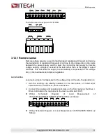
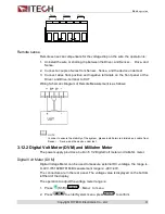
Страница 34: ...his will allow the supply to automatically compensate for the voltage drop in the load leads and improve regulation Local sense Local sense doesn t compensate for the voltage drop on the wire the operation is 1 Use the shorting clip already installed on the rear panel or install wires between Drive and Sense Drive and Sense 2 Connect the positive and negative terminals on the front panel or the Dr...

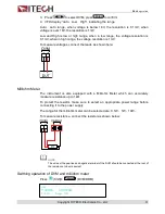
Страница 35: ... NOTE In order to ensure the stability of the system please install armored twisted pair cable from Sense Sense and the device under test 3 12 2 Digital Volt Meter DVM and Milliohm Meter The power supply provides a built in 5 1 2 Digital Volt meter and milliohm meter Digital Volt Meter DVM Digital Voltage Meter can be used to measure external DC volatage the range is 0 40V IT6162B IT6164B measurem...

Страница 36: ... the leads as shown here Milliohm Meter The instrument is also equipped with a Milliohm Meter which can accurately measure resistance up to 1kΩ To protect the resistor make sure to select an appropriate power range before connecting it to the power supply The range for the milliohm meter can be selected are 0 1W 1W 10W To measure resistance connect the resistor as shown below NOTE The wires at the...

Страница 37: ... in milliohm meter mode press Shift can set the rangeto 0 1W Press Shift set the range to 1W Press Shift 3 set the range to 10W 3 13 Power information The information include Model program version serial number SN Operation to check Press Shift Info to check model and program version and to check SN ...

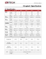
Страница 38: ...Vpp 4mv Vpp 4mv Vpp 5mv Vpp current 3mA rms 3mA rms 3mA rms 4mA rms 3mA rms Setup resolution volage 1mV 1mV 1mV 1mV 1mV current 0 1mA Setup accuracy Voltage 0 03 3mV 0 03 3mV 0 03 6mV 0 03 3mV 0 03 6mV Current 0 05 2mA 0 05 2mA 0 05 1mA 0 05 2 5mA 0 05 1 5mA Readback resolution Voltage 0 1mV 0 1mV 0 1mV 0 1mV 0 1mV current 0 01mA 0 01mA 0 01mA 0 01mA 0 01mA Readback accuracy Voltage 0 02 3mV 0 02 ...

Страница 39: ...tput Offset Voltage 0 02 2mV Current 0 05 15mA Ripple 20Hz 20MHz Voltage 4mVp p 1 2 mV rms Current 15mArms Tem coefficient of Output Offset Voltage 0 01 2mV Current 0 01 20mA Readback Tem coefficient of Output Offset Voltage 0 01 2mV Current 0 01 15mA Rising Time at no load Voltage 1mS Rising time at full load Voltage 1mS Falling time at no load Voltage 50mS Falling time at full load Voltage 1mS D...

Страница 40: ...02 2 mV Display stability 8 h of Output Offset 0 02 2 5 mV Measurement range 40V 40V Parameter IT6164B Rated value 0 40 Voltage 0 30V 0 60V Current 0 40A 0 20A Power 1200W Load regulation of Output Offset Voltage 0 01 10mV Current 0 1 10mA Line regulation of Output Offset Voltage 0 02 2mV Current 0 1 2mA Setup resolution Voltage 1mV Current 1mA Readback resoultion Voltage 1mV Current 1mA Setup acc...

Страница 41: ...age 1 mS 1 2 mS Dynamic response time 200 uS AC input Voltage 220V 10 Frequency 47HZ 63HZ Setup stability 30min of Output Offset Voltage 0 01 2mV Current 0 1 20mA Setup stability 8h of Output Offset Voltage 0 015 2mV Current 0 15 20mA Readback stability 30min of Output Offset Voltage 0 01 2mV Current 0 1 20mA Readback stability 8h of Output Offset Voltage 0 015 2mV Current 0 15 20mA Fuse specifica...

Страница 42: ...0 bit word which has a start bit and a stop bit The start bit and stop bit can not be edited However you can select the parity items with Shift I set I set key on the front panel Parity options are stored in nonvolatile memory Baud Rate The front panel Shift I set I set button allow the user to select a baud rate which is stored in the non volatile memory 4800 9600 19200 38400 57600 115200 RS 232 ...

Страница 43: ...nd PC matches Baud Rate 9600 4800 9600 19200 38400 57600 115200 You can enter the system menu from the front panel and then set the baud rate Data bits 8 Stop Bits 1 Calibration none even odd EVEN 8 data bits have even parity ODD 8 data bits have odd parity NONE 8 data bits no parity Local Address 0 31 the factory default setting is 0 Parity None Start Bit 8 Data Bits Stop Bit 5 2 USB interface Us...

Страница 44: ...the screws Then set the address the address range of the power 0 to 30 can set by the function key on the front panel press the Shift I set I set key to enter the system menu function find the GPIB address setting by button type the address Enter Enter key to confirm GPIB address is stored in nonvolatile memory line 5 4 Communication protocol IT6100B programming should adopt SCPI communication pro...

Страница 45: ...on Length IT E301 10A 10A 1m IT E301 30A 30A 6mm2 1 2m IT E301 30A 30A 6mm2 2m IT E301 60A 60A 20mm2 1 5m IT E301 120A 120A 50mm2 2m IT E301 240A 240A 70mm2 1m IT E301 240A 240A 70mm2 2m IT E301 360A 360A 95mm2 2m For maximum current of AWG copper wire refer to table blow AWG 10 12 14 16 18 20 22 24 26 28 The Maximum current value A 40 25 20 13 10 7 5 3 5 2 5 1 7 Note AWG American Wire Gage it mea...

Страница 46: ...products If you have any doubt about this product please contact us as follow 1 Please refer to the CD ROM of related user s manual in package 2 Visit ITECH website www itechate com 3 Select the most convenient contact for further consultation ...

Отзывы: