


7
.
After
all
measurements
are
completed
,
disconnect
the
test
leads
from
the
circuit
and
multimeter
input
terminals
.
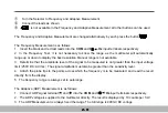
The
Continuity
( )
Measurement
is
as
follows
:
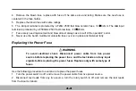
1
.
Select
the
Continuity
Measuremen t
by
Pressing the button
.
2
.
Insert
the
black
and
red
test
leads
into
the
COM
and
V
Ω
Hz
input terminals respectively
.
3
.
Connect
the
black
and
red test probe tips
to
t he
circuit
or
device
under
test
,
making
sure
it
is
de
-
energized first.
4
.
An
audible
tone
will
sound
for
resistance
less
than
approximately
40
Ω
.
5
.
After
Continuity
Measurement
is
completed
,
disconnect
the
test
leads
from
the
circuit
and
multimeter
input
terminals
.
6
.
The
Continuity
Measurement
is
always
fixed
the
range
.
Open
circuit
voltage
approximately
0
.
45V
.
2-18
Содержание M9803R
Страница 1: ...Bench Multimeter Users Manual M9803R...
Страница 8: ...Instrument Layout Figure 1 1 Bench Multimeter Features Forward 1 2...
Страница 9: ...Figure 1 2 Bench Multimeter Features Backward 1 3...
Страница 18: ...Measuring DC Volts Figure 2 1 DC Volts Measurements 2 2...
Страница 20: ...Measuring AC Volts Figure 2 2 AC Volts Measurements 2 4...
Страница 22: ...Measuring DC and AC Amps Figure 2 3 Amps Measurements 2 6...
Страница 24: ...Measuring DC and AC Milliamps Figure 2 4 Milliamps Measurements 2 8...
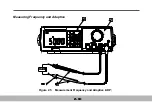
Страница 26: ...Measuring Frequency and Adaptive Figure 2 5 Measurement Frequency and Adaptive ADP 2 10...
Страница 28: ...Measuring Capacitance Figure 2 6 Capacitance Measurements 2 12...
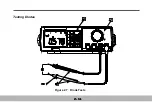
Страница 30: ...Testing Diodes Figure 2 7 Diode Tests 2 14...
Страница 32: ...Measuring Resistance and Continuity Figure 2 8 Resistance and Continuity Measurements 2 16...