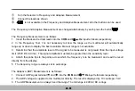
WARNING
Measurements
must
only
be
made
with
the
circuit
power
OFF
.
①
.
Turn
the
Selector
to Diode.
②
.
Connect
the
leads
as
shown
:
Insert
the black and red test leads into
the
COM
and
V
Ω
Hz
input
terminals
respectively
.
③
.
and are not
available
in
the
Diode
test
;
all
other
buttons
can
be
used
.
The
diode
Test
is
as
follows
:
1
.
Set
the
( )
position
by
turning
the
rotary
switch
.
1
.
Insert
the
black
and
red
test
leads
into
the
COM
and
V
Ω
Hz
input terminals respectively
.
2
.
The
red
lead
should
be
connected
to
the
anode
and
the
black
lead
to
the
cathode
of
the
diode
.
3
.
The
typical
voltage
drop
should
be
about
0
.
6Vf
or
silicon
diode
or
0
.
3V
for
germanium
diode
.
4
.
If
the
diode
is
reverse
biased
or
there
is
an
open
circuit
the
reading
displayed
will
be
between
3
.
000V
and
3
.
400V
.
5
.
The
Diode
test
is
always
fixed
the
range
2-15
Содержание M9803R
Страница 1: ...Bench Multimeter Users Manual M9803R...
Страница 8: ...Instrument Layout Figure 1 1 Bench Multimeter Features Forward 1 2...
Страница 9: ...Figure 1 2 Bench Multimeter Features Backward 1 3...
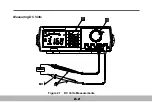
Страница 18: ...Measuring DC Volts Figure 2 1 DC Volts Measurements 2 2...
Страница 20: ...Measuring AC Volts Figure 2 2 AC Volts Measurements 2 4...
Страница 22: ...Measuring DC and AC Amps Figure 2 3 Amps Measurements 2 6...
Страница 24: ...Measuring DC and AC Milliamps Figure 2 4 Milliamps Measurements 2 8...
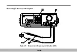
Страница 26: ...Measuring Frequency and Adaptive Figure 2 5 Measurement Frequency and Adaptive ADP 2 10...
Страница 28: ...Measuring Capacitance Figure 2 6 Capacitance Measurements 2 12...
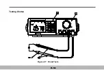
Страница 30: ...Testing Diodes Figure 2 7 Diode Tests 2 14...
Страница 32: ...Measuring Resistance and Continuity Figure 2 8 Resistance and Continuity Measurements 2 16...


