T
he
reference
in
surface
TreaTmenT
International
Surface
Technologies
i s t s u r f a c e . c o m
32
DCM600 to 1800 - Instruction Manual
1.3.3 — locking studs on model pressure
The DCP100A DCP200A and are provided with locking studs to secure the module. In normal operation,
they are not necessary since the clips are sufficient to secure the module even in a high vibration. However,
if the device must be delivered or used in conditions where strong mechanical shock could occur, the pins
lock will ensure that the module does not break into standing out is its support.
To install the locking pin, insert a module below the plot behind each of the two brackets. The entire
insert in the slot. The ends of the studs will depart through the slots at the top of this housing. Next, insert
the module into the panel as shown above, making sure it is properly aligned and that is in place. Press
the locking tabs exposed until the tab is pushed in behind the lock in the table. To remove the module,
slide the locking tabs into place using a small screwdriver and remove the module as described above.
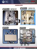
See Figure 3.
1.3.4 — Connections of the dCP
when a pressure module is installed, the 4-20 mA process signal and alarm relay contacts are available. The
4-20 mA circuit is isolated from ground and other signals. The alarm relay contacts are isolated, normally
open contacts. The pressure connections can be made with grooved couplings with hose is 1 / 8 ˝ or 3 /
16 ˝ dia. inside.
Warning: do not force the module into the connectors. insertion force can damage the
connectors. Properly aligned, the module clicks into place.
1.3.5 — Maintenance of dCP
The pressure module should require very little maintenance in normal operation. However, a periodic
calibration may be desirable to ensure accurate readings. The module can be removed and returned to
the factory for calibration.
1.4 — switch connection mode alarm
The automatic alarm reset is controlled by the mode switch for connecting alarm. To enable automatic
alarm reset mode of alarm input to be connected to a common connection. A jumper can be used
when the automatic reset alarm is still active. A switch can be used if there are times when stopping the
automatic alarm should be disabled. The switch must be a single contact and wired, so no connection is
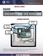
made between one or the other son and the earth. See Figure 2 connections.
1.4.1 — reset connection mode alarm
The alarm can be reset by pressing the reset button on the alarm control panel or by an external switch
connected between the terminal alarm reset and common terminals. The alarm reset only works if the
pressure module is installed and the pressure returned to normal. See Figure 2 connections.
1.4.2 — Connecting the 4-20 ma loop
The pressure module provides an isolated 4-20 mA output, which may be used to remotely monitor the
differential pressure across the dust bags or cartridges. The connection is made on the master control
module at the terminal block designated for this signal. The connection is a 2-wire configuration with the
option of using either an external 15 to 35 V DC power source or using the internal 24 V DC source. See
Figure 2 wiring Connections.
1.0 — installing tHe dCt1000 (Cont’d)
1.0 — installing tHe dCt1000 (Cont’d)

