T
he
reference
in
surface
TreaTmenT
International
Surface
Technologies
i s t s u r f a c e . c o m
31
DCM600 to 1800 - Instruction Manual
1.3.1 location
The system should be located in an enclosure that meets appropriate standards of safety and electrical
codes. There is no other requirement for the particular orientation as pressure module and the orientation
is not critical. The path of the air piping should be particularly studied to ensure that there is no
potential condensation or moisture that flows through the sensor. where there is a high concentration of
condensation present, a gutter or inlet filter should be installed to ensure proper operation in the long
term.
1.3.2 dCP connection to the master controller
The pressure module is attached to the master controller using integrated connectors on both units.
Ports for the insertion pressure module are located in the upper left quadrant of the master controller
DCT1000. The pressure module can be removed by compressing attachments retained each side of the
module, then gently remove the module from the master controller circuit. By inserting the module, the
following procedure should be observed to ensure proper installation:
•
Examine the bottom of the pressure module and note the orientation of the connectors.
•
Align the module so that the connectors match the connector receptacles on the circuit of the
controller.
•
Orient the module with the four blocks of alignment with their respective mounting holes.
•
Gently press the module into the connector and slide the retaining clips on each side of the module
in their homes.
•
Always install and maintain this system with the power off and install a lock if necessary. Connect
the pressure module to «Hot» in a system to damage the system or cause the cancellation of the
calibration parameters.
By installing or removing the module and ensure to guide the module correctly with the table. Installing
or removing the module from any angle can break the alignment pins.
dCP installation
CENTERING
STUDS
PRESSURE
MODULES
LOCkING STUDS
BELOw THE
MODULE ONLY
PCB
INSERT THE LOCkING PINS UNTIL THEY LOCk FIRMLY IN PLACE
LOCkING PIN INSERTED COMPLETELY
INTO HOUSING
1.0 — dCt1000 installation (suite)
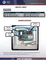
Figure 3

