4
Section
3
ASSEMBLY,LUBRICATION,
INSTALLATION
Note:
These instructions must be followed to insure proper
installation, efficient operation and the prevention
of serious damage to your stitcher.
Before Unpacking:
Examine the outside of the crate or carton for any
visible damage. If damaged DO NOT UNPACK
THE STITCHER. Notify the carrier who deliv-
ered the stitcher.
After Unpacking:
Examine your stitcher carefully for any damage in
transit. If damaged, DO NOT INSTALL THE
STITCHER. Notify your nearest representative and
the carrier who delivered your stitcher.
Make certain that you get a signed copy of the
Carrier Inspectors Report of the damage incurred.
ASSEMBLY
1. Clamp or bolt the M2000 head to your machine
2. Install Wire Guide Spring into wire guide
bracket of M2000 Head.
THREADING WIRE AND
ADJUSTING WIRE
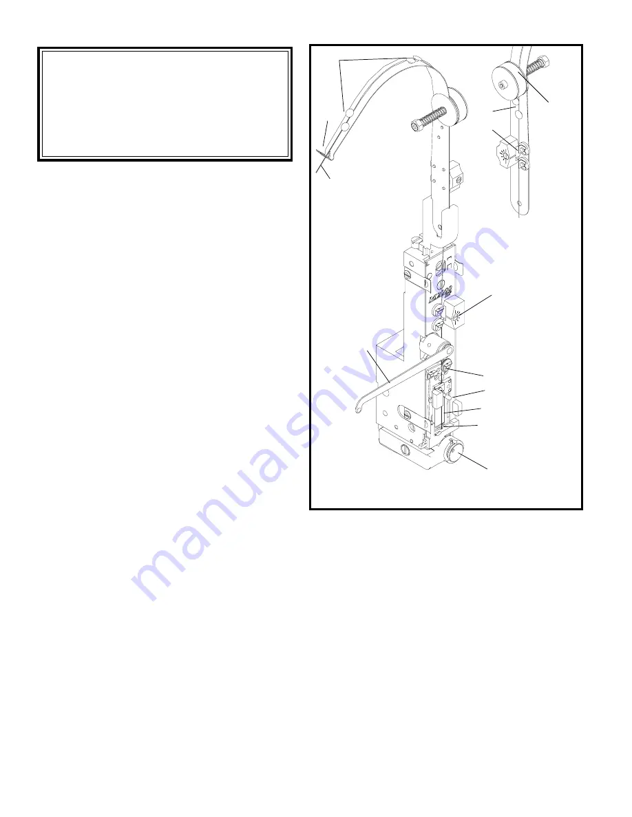
STRAIGHTENERS (See fig. 1)
1. Draw wire (Index A) by hand, from the coil.
2. Thread the wire through the slot (Index B) at
the end of the wire guide spring, , through the
wire guides (Index C), between the thin and
thick felt wire wipes (Index D), through the
upper wire straightener (Index E), and through
the lower wire straightener (Index F).
A (From wire coil)
C
H
G
J
K
F
B
C
E
3. Release the rotator operating spring (Index H)
from the rotator and swing it to the left.
Remove Rotator (Index K).
4. Thread the wire between the tension pawl and
tension roll (Index G). Feed the wire through
the wire cutter lead-in hole (Index I) in the
bottom of the face plate.
5. Push grip post to left to open the grip (Index J).
Insert wire and release the post so that the grip
engages the wire for feeding into the rotator.
6. To check adjustment, hold open grip (Index J
and pull about 1 1\2 feet of wire from below
face plate. Cycle machine once by hand to cut
wire. Cycle machine again by hand to observe
wire straightness. The wire (Index L) should
point straight down, prior to being cut.
I
(CTTT2605 Scene 3, Scene 4)
Figure 1
D
L


