background image

4. Install the riser card support bracket by aligning the top edge of the riser card into the two lance features on the

support bracket.

Note:  Make sure to route the drive cables under the riser card support bracket.

5. Replace the node top panel.

For more information, see 

Installing the node top panel

 on page 35.

6. Connect both power cables to the node power supplies and verify that the node starts properly and displays the login

prompt.

Note:  If a node fails to start properly or the node displays errors relating to the journal, contact Isilon
Technical Support.

Replacing the IB/NVRAM Card

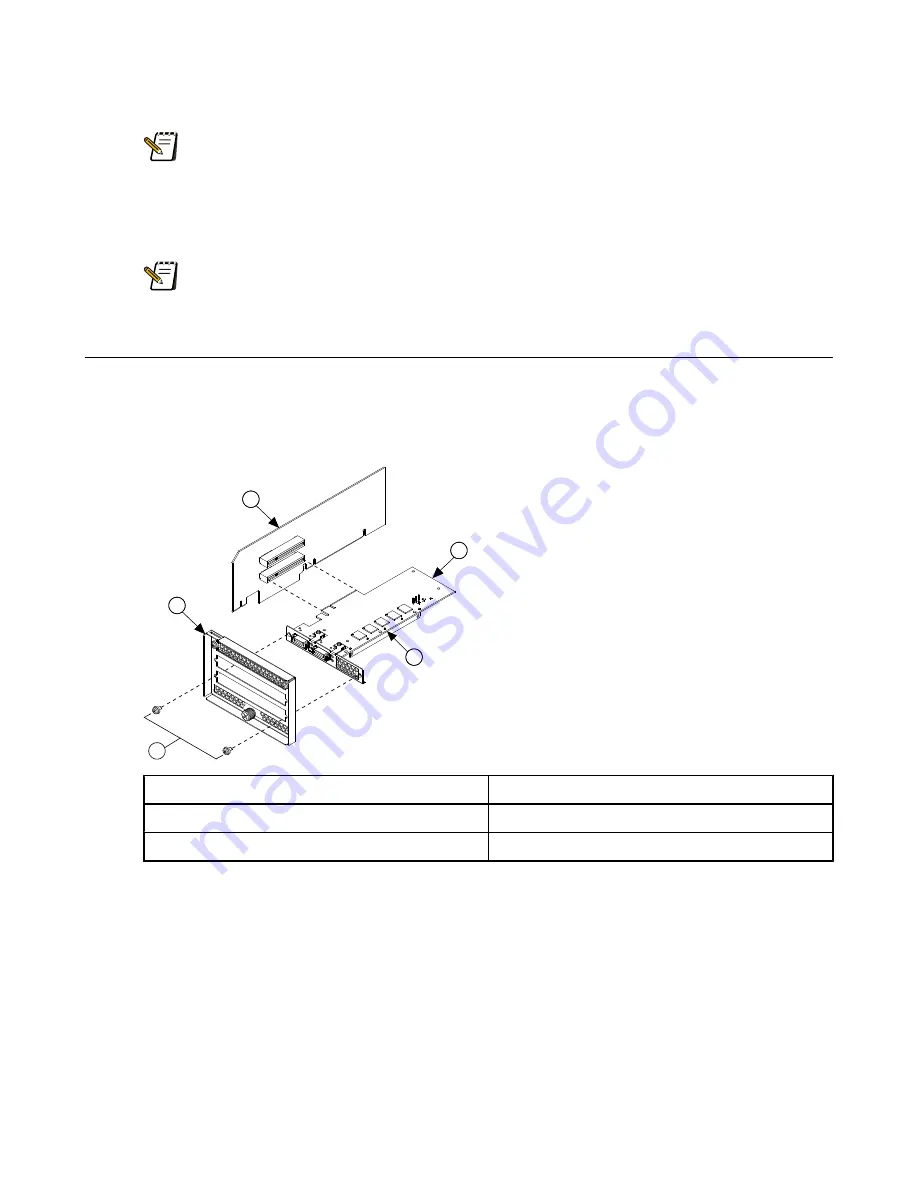
Isilon IQ nodes include a combination InfiniBand/non-volatile RAM (IB/NVRAM) card.

Prerequisite:  Before replacing the IB/NVRAM card, you must remove the PCIe riser card assembly. For more
information, see 

Removing the riser card assembly

 on page 27.

1. Disconnect the IB/NVRAM 8-position cable from the back of the IB/NVRAM card.

2

3

4

5

1

1  Mounting screws

4  8-position cable connector

2  Rear I/O panel

5  IB/NVRAM card

3  PCIe riser card

Figure 16. Removing the IB/NVRAM card

2. Remove the two mounting screws on the rear I/O panel.

3. Remove the IB/NVRAM card.

4. Insert the new IB/NVRAM card into the bottom slot on the PCIe riser card.

5. Connect the 8-position cable to the back of the IB/NVRAM card.

6. Secure the IB/NVRAM card to the rear I/O panel using the two small screws that you removed in a previous step.

7. Install the riser card assembly.

8. Return the old hardware to Isilon Technical Support.

For more information, see 

General recommendations

 on page 5.

Expansion cards

©

 2010 Isilon Systems, Inc.

31

Содержание IQ S Series

Страница 1: ...Isilon IQ S Series Field Replacement Manual August 2010 120 0031 01 Rev C ...

Страница 2: ... company names mentioned are the trademarks of their respective owners U S Patent Numbers 7 146 524 7 346 720 7 386 675 7 509 448 7 509 524 7 551 572 7 590 652 7 593 938 China Patent Number ZL 02816665 5 Other patents pending Due to ongoing product development innovation and revision the information contained here is subject to change without notice Isilon will publish updates and revisions to thi...

Страница 3: ...r 5 Hard drives 13 Replacing a failed hard drive 13 Adding an SSD to a 5400S node 15 Chapter 6 Cooling fans 19 Replacing a fan 19 Chapter 7 DIMM modules 23 Replacing a DIMM module 23 Chapter 8 Expansion cards 27 Removing the riser card assembly 27 Installing the riser card assembly 29 Replacing the IB NVRAM Card 31 Replacing the SAS drive controller card 32 Replacing the network interface card 33 ...

Страница 4: ...Chapter 11 Air baffle 39 Removing the air baffle 39 Installing the air baffle 40 ...

Страница 5: ... such as a node connected to a power strip Before performing maintenance on Isilon nodes disconnect both power cables Do not overload the branch circuit of the AC power supply providing power to the rack cabinet containing Isilon nodes The total rack load must not exceed 80 percent of the branch circuit rating To help protect the system from sudden increases or decreases in electrical power use a ...

Страница 6: ...sis and evaluation To return a component to Isilon contact Isilon Technical Support and follow the instructions provided by the support engineer Make sure to include the following details about the failed component on a label or packing sheet Serial number of node Technical Support case number if any Slot number or drive number if applicable Brief description of the failure circumstances Component...

Страница 7: ...at secures the node to the rack cabinet 2 Slide the node out several inches from the rack cabinet to allow clear access to the node front panel and hinges 3 Remove the front panel and hinges from the node by removing the four screws that secure the front panel and hinges to the node chassis 4 Install the right and left hinge brackets onto the new front panel using the provided shoulder screws 5 Al...

Страница 8: ......

Страница 9: ...other system components You must use a wrist strap attached to the node chassis for grounding Required hardware Replacement power supply ESD grounded wrist strap Replacing a power supply Caution Never remove both power supply units from a running node Note Replacing a power supply does not require powering down the node The remaining power unit provides enough power for the node 1 Check the LED on...

Страница 10: ... supply from the node 4 Insert a new power supply into the empty power supply bay with the label side facing up 5 Push the new power supply firmly but carefully into the bay The retaining latch automatically clicks into place to secure the power supply 6 Connect a power cord to the new power supply The LED on the power supply turns green when the power supply begins supplying power to the node 7 R...

Страница 11: ...D prevention procedures when removing and replacing cards memory and other system components You must use a wrist strap attached to the node chassis for grounding Required hardware Replacement non volatile RAM NVRAM battery assembly ESD grounded wrist strap Replacing an NVRAM battery assembly After an alert is issued it is important to replace the NVRAM battery as soon as possible After an alert i...

Страница 12: ...ed by an INFO alert stating that the new battery is undergoing a rapid test 6 Wait five minutes for the rapid battery test to conclude If the test concludes successfully the INFO alert stops the red Service LED turns off and the node returns to read write mode Note If the battery test does not complete successfully remove the battery assembly and insert another battery assembly 7 Verify that the C...

Страница 13: ...inimize the potential for data loss Caution Do not remove a healthy drive from a node unless instructed to remove the drive by Isilon Technical Support Drive bays are numbered left to right top to bottom For example the top row of bays on the front of a node are numbered 1 4 1 Identify the failed hard drive If you already know which hard drive to replace proceed to the next step To determine which...

Страница 14: ...ify an SSD by the color of the drive tray locking handle SSDs have silver handles whereas all other drive types have black handles SSDs are also smaller 2 1 2 drives 7 Gently push the locking handle on the drive until the drive clicks into place 8 Close the node front panel 9 Slide the node back into the rack cabinet 10 Secure the node to the rack cabinet using the chassis mounting screw 11 On the...

Страница 15: ... been re inserted follow the instructions provided in the error message or contact Isilon Technical Support 13 Return the old hardware to Isilon Technical Support For more information see General recommendations on page 5 Adding an SSD to a 5400S node This procedure describes how to upgrade an Isilon IQ 5400S node to a fully supported Isilon IQ 5000S SSD node Prerequisite Note This upgrade is avai...

Страница 16: ...oteV Steps 1 10 must be repeated for each node on the cluster 1 Update the system configuration number by running the following command echo NPEFM OVNCFS etc isilon_system_config isi_dongle_sync p 2 Replace the SAS drive in Bay 1 with an SSD 3 Restart the isi_drive_d daemon by running the following command isi_drive_d restart 4 Add the drive by running the following command isi devices f a add d b...

Страница 17: ... all nodes on the cluster have been updated with SSDs When all of the nodes have been updated continue to the next step 12 From any node on the cluster perform the following actions These actions will be applied to all nodes on the cluster 1 Run the following commands sysctl efs bam layout min_free_drive_blocks 3000 echo efs bam layout min_free_drive_blocks 3000 etc mcp override sysctl conf Runnin...

Страница 18: ......

Страница 19: ...dware Replacement cooling fan ESD grounded wrist strap 2 Phillips screwdriver or 2 JIS driver Replacing a fan Note Replacing a fan does not require powering down the node 1 Remove the top panel from the node For more information see Removing the node top panel on page 35 Note Removing the top panel from a node temporarily places the node into a read only state The node returns to a read write stat...

Страница 20: ...moving a fan 4 Slide the new fan into the fan sleeve in the correct orientation 5 Lift the release lever to engage the fan latch on the release lever side of the fan 6 Press the fan straight down and secure the fan latch on the opposite side of the release lever The fan should begin spinning and the Fan Fault LED should turn off 7 Replace the node top panel For more information see Installing the ...

Страница 21: ...8 Return the old hardware to Isilon Technical Support For more information see General recommendations on page 5 Cooling fans 2010 Isilon Systems Inc 21 ...

Страница 22: ......

Страница 23: ... run the isi_dmilog command The system displays information similar to the following example output Log 03 28 10 10 18 13 CDT Correctable ECC memory error 1 time on DIMM1A 03 28 10 10 18 13 CDT Non PCI non fatal error 1 time on ich esi pci Totals 1 of Non PCI non fatal error 1 of Correctable ECC memory error This example output shows that there is an error with DIMM1A which means that the DIMM mod...

Страница 24: ...move the air baffle For more information see Removing the air baffle on page 39 9 Locate the DIMM module you want to replace 2 1 3 1 Air baffle 3 DIMM modules 2 PCIe riser card support bracket Figure 9 DIMM module location 10 Gently press the two DIMM socket arms on either side of the DIMM module to release the DIMM module from the socket DIMM modules 24 2010 Isilon Systems Inc ...

Страница 25: ...r baffle For more information see Installing the air baffle on page 40 15 Replace the node top panel For more information see Installing the node top panel on page 35 16 Connect both power cables to the node power supplies and verify that the node starts properly and displays the log in prompt Note If a new DIMM is not properly installed or is corrupt the node will beep during the startup process ...

Страница 26: ......

Страница 27: ...n be one of the following types InfiniBand non volatile RAM IB NVRAM card Serial attached SCSI SAS card GigE or 10 GigE network interface card NIC ESD grounded wrist strap 2 Phillips screwdriver or 2 JIS driver Removing the riser card assembly 1 From the command line interface enter shutdown p now to shut down the node 2 Unplug both power cables from the back panel of the node 3 Remove the top pan...

Страница 28: ...ear panel of the node loosen the captive screw on the I O panel Note The SAS2 and SAS3 ports shown in this figure are not used and are not included in newer SAS drive controller cards 1 1 I O panel captive screw Figure 12 Isilon IQ S Series rear panel 6 Press the release lever on the triangular support bracket and slide the bracket forward to allow the riser card assembly to be removed Expansion c...

Страница 29: ...cing the SAS drive controller card Also do not disconnect the 8 position cable assembly from the InfiniBand non volatile RAM IB NVRAM card unless you are replacing the IB NVRAM card Installing the riser card assembly Installing the riser card assembly connects the SAS drive controller card and the IB NVRAM card to the node motherboard 1 Insert the riser card assembly into the PCI Express PCIe slot...

Страница 30: ... assembly 2 Tighten the captive screw on the rear I O panel Note The SAS2 and SAS3 ports shown in this figure are not used and are not included in newer SAS drive controller cards 1 1 I O panel captive screw Figure 15 Isilon IQ S Series rear panel 3 Slide and lock the triangular support bracket into position to support the front edge of the SAS drive controller card Expansion cards 30 2010 Isilon ...

Страница 31: ...replacing the IB NVRAM card you must remove the PCIe riser card assembly For more information see Removing the riser card assembly on page 27 1 Disconnect the IB NVRAM 8 position cable from the back of the IB NVRAM card 2 3 4 5 1 1 Mounting screws 4 8 position cable connector 2 Rear I O panel 5 IB NVRAM card 3 PCIe riser card Figure 16 Removing the IB NVRAM card 2 Remove the two mounting screws on...

Страница 32: ...AS drive controller card 3 Remove the two mounting screws on the rear I O panel 1 2 3 4 5 1 SAS drive controller card mounting screws 4 Hard drive cable connection port 2 Rear I O panel 5 SAS drive controller card Note The SAS2 and SAS3 ports shown in this figure are not used and are not included in newer SAS drive controller cards 3 PCIe riser card Figure 17 Removing the SAS drive controller card...

Страница 33: ...From the command line interface enter shutdown p now to shut down the node 2 Unplug both power cables from the back panel of the node 3 Unplug the External 3 and External 4 network cables 4 Remove the top panel from the node For more information see Removing the node top panel on page 35 5 Loosen the captive screw that secures the riser card support bracket pivot the bracket toward the back of the...

Страница 34: ...nstall the air baffle For more information see Installing the air baffle on page 40 12 Install the riser card support bracket by aligning the top edge of the riser card into the two lance features on the support bracket Note Make sure to route the drive cables under the riser card support bracket 13 Replace the node top panel For more information see Installing the node top panel on page 35 14 Con...

Страница 35: ...e slide rails and provide clear access to the node top panel Note To remove the top panel while a node is running the node must have sufficient cable length or service loop to fully extend the slide rails without disconnecting the cables 3 Remove the single screw securing the node top panel 4 Slide the top panel toward the rear of the node and lift the top panel off to access the node interior Not...

Страница 36: ......

Страница 37: ...ist strap 2 Phillips screwdriver or 2 JIS driver Side cutter or other tool to cut cable ties Replacing a SATA cable 1 Type shutdown p now to shut down the node 2 Unplug both power cables from the back panel of the node 3 Remove the top panel from the node For more information see Removing the node top panel on page 35 4 Before removing a serial ATA SATA cable make a note of the cable connections a...

Страница 38: ...er Port number Cable 0 Port 1 Port 2 Port 3 Port 4 Cable 1 Port 5 Port 6 Port 7 Port 8 Cable 2 Port 9 Port 11 Port 13 Port 15 7 Install the node top panel For more information see Installing the node top panel on page 35 8 Connect both power cables to the node power supplies and verify that the node starts properly and displays the login prompt Note If a node fails to start properly or the node di...

Страница 39: ...ocedures when removing and replacing cards memory and other system components You must use a wrist strap attached to the node chassis for grounding Required hardware ESD grounded wrist strap 2 Phillips screwdriver or 2 JIS driver Removing the air baffle 1 From the command line interface enter shutdown p now to shut down the node 2 Unplug both power cables from the back panel of the node 3 Remove t...

Страница 40: ... NVRAM 8 position cable connector 5 PCI riser card assembly 3 Rear I O panel captive screw 6 Air baffle Figure 21 PCI riser card assembly 5 Remove the white air baffle Installing the air baffle 1 Lower the air baffle into an open node chassis Air baffle 40 2010 Isilon Systems Inc ...

Страница 41: ... tabs in the fan wall Note Make sure to route the drive cables over the air baffle 5 Install the riser card support bracket by aligning the top edge of the riser card into the two lance features on the support bracket Note Make sure to route the drive cables under the riser card 6 Replace the node top panel For more information see Installing the node top panel on page 35 7 Connect both power cabl...

Страница 42: ......

Страница 43: ...dex C cluster maintenance overview 5 returning parts 5 safety 5 I Isilon Technical Support 6 P parts returning 5 R returning parts 5 S safety precautions 5 support technical 6 T Technical Support Isilon 6 ...

Страница 44: ......

Отзывы:

Похожие инструкции для IQ S Series