background image


Chapter 3 Adjustment Mode 


3.2.6 

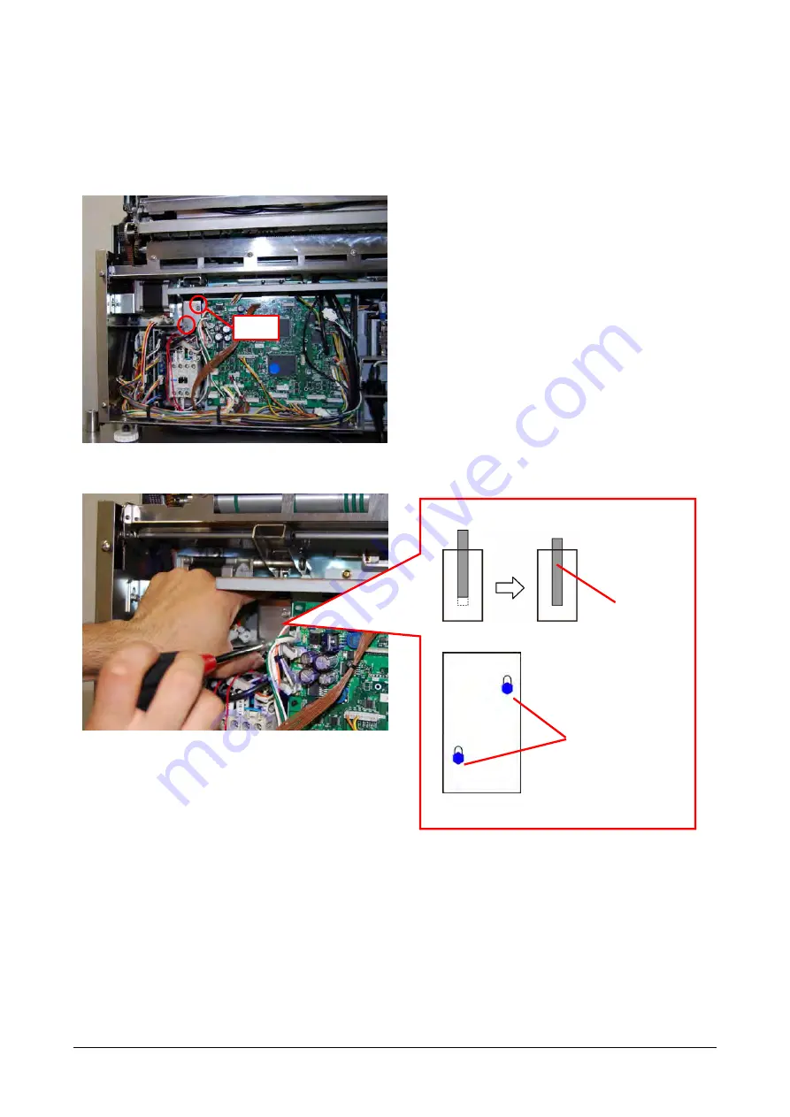
Adjusting Cutter Solenoid Position 

Fix the cutter solenoid with screws (2) at the position where the iron core is the most inside of the solenoid. 

1

  Turn the machine power switch OFF. 


2

  Loosen the screws (2) that fix the cutter solenoid. 


3

  Screw holes are elongated allowing vertical position adjustment. Fix the solenoid with screws (2) at the

position where the iron core is the most inside of the solenoid. 


Screw 

Set the solenoid at the position where the 
iron core is the most inside of the solenoid. 


Iron core

 
Fix with screws (2). 


Elongated 
holes 


 3-49 

Содержание WM-NANO

Страница 1: ...RTANT Do not carry out installation operation service or maintenance until thoroughly understanding the contents of this manual Keep this manual available at all times for installation operation service and maintenance PN 154792 ...

Страница 2: ...s are reserved No part of this publication may be reproduced stored in a retrieval system or transmitted in any form or by any means mechanical electronic photocopying recording or otherwise without prior written permission of ISHIDA ...

Страница 3: ...cording to proper procedures by a qualified person and only for the purposes described in this manual The following conventions are used to indicate and classify precautions depending on the level of danger or seriousness of potential injury Always heed the information provided in this manual and the stickers put on the machine Failure to heed precautions may result in personal injury or property ...

Страница 4: ... and Setting 1 9 1 7 1 Handling of Controller Uni 7 RP 1 9 1 7 2 Carrying the Machine 1 9 1 7 3 Setting on the Stand or the Table 1 11 1 7 4 Setting on the Ishida Stand 1 12 1 7 5 Cabling between UNI 7 and Wrapper 1 13 Chapter 2 Functions for Each Mode 2 1 2 1 Normal Mode 2 2 2 1 1 Return Process at Power ON 2 2 2 1 2 How to Use Preset Keys 2 3 2 2 PROGRAM Mode 2 9 2 2 1 WRAP Tab Added to PLU 2 9 ...

Страница 5: ... 3 2 9 Adjusting Squeeze Amount of the Postsqueezing Plate 3 52 3 2 10 Adjusting Discharge Pusher Standby Position 3 53 3 2 11 Adjusting Tray Holder Height 3 54 3 2 12 Adjusting Claw Height of the Infeed Unit 3 55 Chapter 4 Hardware Electrical 4 1 4 1 Electrical Unit Board Configuration 4 1 4 1 1 Alignment of Each Control Unit 4 1 4 1 2 Front Weighing Unit 4 2 4 1 3 Wrapping Control Unit 1 2 4 3 4...

Страница 6: ...Introduction 6 ...

Страница 7: ...ingle Phase 50 60 Hz No component change required for change of power supply frequency Packs Per Minute Up to 15 packs min Wrapping Capacity M Type 20 to 1500 g L Type 20 to 3500 g Weighing Capacity 0 04 to 15kg Weight Wrapper Block M Type 94 6 kg L Type 102 4 kg or less UNI 7 RP 10 kg or less Noise 73 dB or less 1 1 2 Wrapper Specifications I t e m D e t a i l s Wrapping Method Stretch Wrapping W...

Страница 8: ...Method Belt Transfer Full Cut Film Weld Roller type with cartridge heater Do not leave a tray on the heater If sealing strength is not enough press it on the roller again Cleanability Detachable lift head water washable except for the movable block of the head Detachable weighing table water washable Detachable garbage plate of the weighing block water washable 1 1 3 Operation Unit Specifications ...

Страница 9: ... i l s Service Life 5 years except for consumables Conditions Operating in 1000 packs day 350 days year 4200 hours 1 75 million packs for 5 years 21000 hours Safety Complying to Ishida s product safety and warning indication standards ETL CE C Tick Standards Ishida s product standards and measurement laws of specified countries ...

Страница 10: ...Chapter 1 Overview 1 2 Part Names 1 2 1 Appearance 1 4 ...

Страница 11: ...Chapter 1 Overview 1 5 ...

Страница 12: ...Chapter 1 Overview 1 3 Outline Dimensional Drawings 1 3 1 Dimensions Dimensions are shown below Provide enough space for carry in route setup and maintenance M type Film L type Film 1 6 ...

Страница 13: ...FOLLOWING PRECAUTIONS ABOUT POWER SUPPLY Use a power supply with rated voltage ground Prepare a dedicated power source A power supply that generates voltage variation may cause a malfunction Do not stand on the power cord and do not place anything heavy on the cord Doing so may damage the cord resulting in accident or trouble 1 7 ...

Страница 14: ...or Unpacking Before Unpacking After Unpacking Do not use a lift under the product to carry The product must be carried by hand Insert hands to the holes red circled in the picture below to lift and carry the product after unpacking 1 8 ...

Страница 15: ...While the stand in the pictures below is the older type instructions for carry and installation are not changed 1 7 1 Handling of Controller Uni 7 RP Please always remove the controller Uni 7 RP when you move the machine for the safety purpose 1 7 2 Carrying the Machine When carrying the machine please hold the part between the truss head screws below picture at the back B and the bottoms of left ...

Страница 16: ...A B DO NOT HOLD When moving the machine by a trolley please put it on a flat surface trolley Note Please make sure that the jack legs of the machine at the bottom side are on the trolley Jack legs position 1 10 560 mm 500 mm Bottom side Jack legs ...

Страница 17: ...ility than the constitution example written below before the setup A 40 mm B C 50 mm D Constitution example Material of each part A SUS board thickness 2mm 0 08 Boxed type shape B SUS board thickness 2mm 0 08 L shape C SUS board thickness 2mm Boxed type shape D SUS board thickness 3mm Please be careful not to pinch your hands between the stand or the table and the machine when you put the machine ...

Страница 18: ...tween the stand especially the pronging part of the top table red arrow parts and the machine when you put the machine on Adjust the pronging part of the top table of the stand red arrow parts and screw holes at the bottom of the machine blue arrow parts Bottom of the machine Top table Bottom of the stand Complete 1 12 ...

Страница 19: ... NANO with M3 SEMS screws accessory of WM NANO Wrapper end Power cable L shaped bracket UNI 7 end M4 TP screws 2 Power cable U shaped bracket M3 SEMS screws Communications Cable for Wrapper 1 Remove the plate and 2 countersunk screws and attach the communications cable to UNI 7 2 Attach the plate with the 2 countersunk screws Slack off the communications cable and use with the clamp with M3 TP scr...

Страница 20: ...e Adjusting Gap between UNI 7 and Wrapper Rotate UNI 7 s adjusting feet to adjust the height so that the gap between UNI 7 and the wrapper unit should be about the diameter of the cable If the gap between UNI 7 and the wrapper is insufficient the cable may be damaged due to stress Gap between UNI 7 and wrapper Diameter of the cable Adjusting feet 1 14 ...

Страница 21: ...djust the end plane If setting 350 mm film to M type Shift the film s end face by 10 mm to the back from the roller s end face to set the film 350 mm film Film end face Roller end face Keep 10 mm gap After adjusting the front end keep 1 mm gap between the film roll and the film guide surfaces on the back end Too much force on the film roll by the film guide may interfere with film roll rotation 1 ...

Страница 22: ... Tab Added to PLU Preset Keys Added PROGRAM Mode TRAY Added to Menu FUNCTION KEY Items Added to KEY LOCK Items Added to PLU OVERWRITE WRAP Tab Added to PLU INITIAL DATA Items Added to PLU UPDATE COUNTRY MISC Screen Added SETUP Mode Tray Master Added to FILE SAVE LOAD MEMORY CLEAR Items Added SUB Tab Added to DOWN LOAD WRAPPER Added to Menu UNIT TEST Added to Menu ADJUST Mode WM NANO Added to MODEL...

Страница 23: ...confirmation for the return process 1 A screen appears when the power is turned on that requires confirmation for the return process of each drive unit 2 Touch the RETURN button temporarily displays a screen as shown below __ 3 A screen appears that requires confirmation of the clock Check the date and time then touch the ENTER button __ 2 2 ...

Страница 24: ... to WM NANO TRAY No WRAP ADJUST CLEANING HEATER ADJUST WRAP STATUS WRAP MODE VOLUME FILM REMOVE FILM FEED RETURN TRAY No Enter a tray number and touch the TRAY No preset key A screen for the specified tray appears If no tray number is entered the tray list screen appears WRAP ADJUST Touch the WRAP ADJUST preset key 2 3 ...

Страница 25: ...ing enter a relative value and touch the RETURN button FRONT CLAMP Adjusts the film tension with the front clamp The larger the clamping time larger value the larger the film tension becomes The smaller larger value the smaller the tension becomes REAR CLAMP Adjusts the film tension with the back clamp The larger the clamping time larger value the larger the film tension becomes The smaller larger...

Страница 26: ...e lift and the left and right squeezing plates move toward the end for better cleaning When you are ready for cleaning touch the START button HEATER ADJUST Touch the HEATER ADJUST preset key The HEATER ADJUST screen appears To change the setting enter a value and touch the SET button 2 5 ...

Страница 27: ...temperature Value range 80 to 170 POWER Switches on off the film sealing heater power FAN HEATER TEMPERATURE C Configures the fan heater temperature Value range 0 to 40 C POWER Switches on off the fan heater power FILM TENSION Adjusts the film tension Enter a relative value Value range 4 to 4 2 6 ...

Страница 28: ...d SEAL HEATER IS POWER ON The film sealing heater is on Blue Low Green Normal setup value 10 C Red High WRAP MODE Touching the WRAP MODE preset key allows you to switch between wrapping modes of the product master You can select from WRAP PRINT WRAP PRINT for WRAP MODE VOLUME Touching the VOLUME preset key allows you to switch between volumes the product master You can select from FLAT LOW MIDDLE ...

Страница 29: ...MOVE Touching the FILM REMOVE preset key allows you to cut the film and remove it from the wrapper FILM FEED Touching the FILM FEED preset key feeds the film RETURN Touching the RETURN preset key performs return process of the drive units 2 8 ...

Страница 30: ...r 1 Touch PLU in the PROGRAM mode screen If PLU is not displayed touch or button until it appears 2 The PLU DETAIL SALE1 screen appears 3 Touch the WRAP tab Configure WRAP MODE TRAY No and VOLUME WRAP MODE Select from 1 WR PR initial value 2 PRINT 3 WRAP TRAY No Specify a value in a range from 0 to 9999 The initial value is 0 VOLUME Select from 0 NON initial value 1 LOW 2 MIDDLE 3 HIGH 2 9 ...

Страница 31: ...AY No WRAP ADJUST CLEANING HEATER ADJUST WRAP STATUS WRAP MODE VOLUME FILM REMOVE FILM FEED RETURN For details of the added preset keys see of the normal mode 1 Touch PRESET KEY in the PROGRAM mode screen If PRESET KEY is not displayed touch or button until it appears 2 The PRESET KEY PANEL screen appears Enter a tray number and touch a key to which you want to assign the tray 2 10 ...

Страница 32: ...ded to Menu 1 Touch TRAY in the PROGRAM mode screen If TRAY is not displayed touch or button until it appears 2 A list of registered trays appears in the TRAY screen Change Select a tray and touch the DETAIL button New registration Touch a blank field DETAIL Displays the selected tray DELETE Resets the selected tray information to the default 2 11 ...

Страница 33: ...he tray information acquired by entering the tray number to the current tray RETURN Returns the mechanism to the initial positions DELETE Deletes the tray being selected 4 Touching the ADJUST1 tab displays the TRAY ADJUST1 screen You can adjust the tray information setting FRONT CLAMP Adjusts the film tension with the front clamp The larger the clamping time larger value the larger the film tensio...

Страница 34: ...e the setting unless you are qualified to do so To display the TRAY ADJUST2 screen the password is required FRONT CLAMP Adjusts the film tension with the front clamp The larger the clamping time larger value the larger the film tension becomes The smaller larger value the smaller the tension becomes REAR CLAMP Adjusts the film tension with the back clamp The larger the clamping time larger value t...

Страница 35: ...ase use L R FOLDERS Tray Tray Squeezing plates Squeezing plates Need to be moved further insides The default wrapping conditions are calculated based on the tray width depth and height Specify a relative value from the default for each item Specifying a 5 value for an item configures the operation as 5 timing or amount to its default value Common items are linked between TRAY BASIC TRAY ADJUST1 an...

Страница 36: ...TUP mode screen enter 495344 and touch the PLU key The hidden menu appears 2 3 2 FUNCTION KEY Items Added to KEY LOCK The following items are added to the FUNCTION KEY tab of KEY LOCK WARP MODE TRAY TRAYNo TRAYNAME WRAP ADJUST HEATER ADJUST VOLUME CLEANIG 1 Touch KEY LOCK in the SETUP mode screen If KEY LOCK is not displayed touch or button until it appears 2 15 ...

Страница 37: ...2 The KEY LOCK DISPLAY KEY screen appears Touch the KEY LOCK FUNCTION KEY tab The items in the red frames shown below have been added Touch or button to display an item you want 3 To change the KEY LOCK touch YES or NO in the item 2 16 ...

Страница 38: ...E VOLUME have been added to PLU OVERWRITE 1 Touch PLU OVERWRITE in the SETUP mode screen If PLU OVERWRITE is not displayed touch or button until it appears 2 The PLU OVERWRITE screen appears Touch or button to display an item you want The items in the red frames shown below have been added 2 17 ...

Страница 39: ...ETUP mode screen If PLU INITIAL DATA is not displayed touch or button until it appears 2 The PLU INITIAL DATA screen appears Touch the WRAP tab 3 Configure WRAP MODE TRAY No and VOLUME WRAP MODE Select from 1 WR PR initial value 2 PRINT 3 WRAP TRAY No Specify a value in a range from 0 to 9999 The initial value is 0 VOLUME Select from 0 FLAT initial value 1 LOW 2 MIDDLE 3 HIGH 2 18 ...

Страница 40: ...ray list screen appears You can select a tray to configure 2 3 5 Items Added to PLU UPDATE Items of TRAY No WRAP MODE VOLUME have been added to PLU UPDATE 1 Touch PLU UPDATE in the SETUP mode screen If PLU UPDATE is not displayed touch or button until it appears 2 The PLU UPDATE screen appears 2 19 ...

Страница 41: ...Chapter 2 Functions for Each Mode 3 Touch or button to display an item you want The items in the red frames shown below have been added 2 20 ...

Страница 42: ...s not displayed touch or button until it appears 2 The COUNTRY screen appears Touch the MISC button 3 The COUNTRY MISC screen appears You can change a temperature unit and or configure network connection TEMPERTURE Switches the temperature indication between C Celsius and F Fahrenheit PLU S WRAP PARAMETER RECEIVE When the product master is sent from the host system items related to the wrapper are...

Страница 43: ...r TRAY No VOLUME WRAP MODE 2 3 7 Tray Master Added to FILE SAVE LOAD The tray master has been added to the master list of FILE SAVE LOAD 1 Insert a USB memory stick to the USB connector 2 Touch FILE SAVE LOAD in the SETUP mode screen If FILE SAVE LOAD is not displayed touch or button until it appears 3 The FILE SAVE LOAD USB SCALE screen appears Touching the DETAIL button allows fine adjustment of...

Страница 44: ...To input a tray master from a USB memory stick Select a tray master and touch EXECUTE To output to a USB memory stick Touch the SCALE USB tab Select a tray master and touch EXECUTE To delete a tray master in a USB memory stick Touch the USB DATA DEL tab Select a tray master and touch EXECUTE 2 23 ...

Страница 45: ...pter 2 Functions for Each Mode To initialize an internal tray master Touch the SCALE INIT tab Select a tray master and touch EXECUTE 5 The confirmation screen appears To execute touch the EXEC button 2 24 ...

Страница 46: ... 1 In the ADJUST mode screen enter 495344 and touch the PLU key The hidden menu appears 2 4 2 MEMORY CLEAR Items Added The items of database and image files have been added to MEMORY CLEAR 1 Touch MEMORY CLEAR in the ADJUST mode screen If MEMORY CLEAR is not displayed touch or button until it appears 2 Touch an item you want to perform memory clear 2 25 ...

Страница 47: ...master tray master DATA BASE Specifies which memory should be used to create database After changing the setup you need to restart the power and initialize the memory IMAGE FILE Specifies which memory should be used to create image data MEMORY SIZE Displays SRAM FLASH SDRAM and CF memory 3 The confirmation screen appears To execute touch EXEC 2 4 3 SUB Tab Added to DOWN LOAD 1 Insert a USB memory ...

Страница 48: ...ACHINE NAME Specifies a destination peripheral device for downloading MAIN Specifies a program in the main unit s flash ROM as the source SUB Specifies a program in the USB memory as the source EXECUTE Executes download 5 The confirmation screen appears To execute touch EXEC 2 27 ...

Страница 49: ...ng in each tab To initialize wrapper setting or wrapping count Touch the INITIAL tab To initialize the wrapper setting touch the INIT button To clear the wrapping count touch the CLEAR button INITIAL WRAPPER RESULT Displays the execution result of the initialization INIT button Initializes the wrapper setting data WRAP COUNT TOTAL COUNT Displays the accumulated wrapping count PER COUNT Displays th...

Страница 50: ...onveying operation Use this setting if the film is hard to peel off from the roll FILM CENTERING ADJ Adjusts the stop position of the film for feeding Forward Moving to the right film conveying direction Backward Moving to the left The input range is from 99 to 99 The initial value is 0 FILM LENGTH ADJ Adjusts the length of the film for feeding Forward Longer Backward Shorter The input range is fr...

Страница 51: ...termine that there is no film detected MEASURED VALUE Displays the actual time of film detection 2 4 5 UNIT TEST Added to Menu The UNIT TEST has been added to the ADJUST mode menu You can use this function to operate the units for test 1 Touch UNIT TEST in the ADJUST mode screen If UNIT TEST is not displayed touch or button until it appears 2 Select a unit you want to operate and touch EXECUTE If ...

Страница 52: ...y 0 means operation stop EXECUTE Operates the unit of the specified number KEY UNLOCK KEY ONLY STOP Releases the key lock Locks the key 2 4 6 WM NANO Added to MODEL 1 Touch MODEL in the ADJUST mode screen If MODEL is not displayed touch or button until it appears 2 The MODEL screen appears Select a UNI 7 model and WM NANO connection and type 2 31 ...

Страница 53: ...SELECT Select a UNI 7 model WM NANO Select whether WM NANO is to be connected or not WM NANO TYPE Select a WM NANO type 3 After configuration switching the screen displays the following screen Turn off the power once and turn it on again 2 32 ...

Страница 54: ...Infeed Unit Infeed unit after being removed Infeed unit 1 Remove the weighing table 2 Remove the garbage tray 3 Remove the screws 4 on both sides to remove the front cover Weighing table Garbage tray Lower screws To be removed Upper screws To be loosened Front cover 3 1 ...

Страница 55: ... machine 5 Remove the front right cover Loosen the screws 3 Remove the screw 1 Remove the screw 1 Front right cover The screw position of the front right cover may differ depending on specifications In the configuration shown below remove the screw from the bottom Front right cover 3 2 ...

Страница 56: ...m the hinge of the cover 7 Release the coupling between the infeed arm and the infeed bar c Remove the screw 1 of the infeed arm d Lift the notch of the infeed arm coupling part by sliding the notch to the right Loosen the screws on the front side Remove the screw Loosen the screws Right lateral cover Notch of the infeed arm coupling part Infeed bar Tab 3 3 ...

Страница 57: ... Remove left and right side screws 3 that fix the infeed unit to the machine body 9 Remove the infeed unit from the left and right side notches in the back Right side Screws in the back Notch Notch Screw in the back Left side 3 4 ...

Страница 58: ...Chapter 3 Adjustment Mode 10 Remove the communication cable stored in the right lateral rail 11 Pull out the infeed unit from the machine body Rail Communicati on cable 3 5 ...

Страница 59: ...eing removed Removing the cover 1 Remove the screws 4 that fix the front right cover to remove the cover Remove the screw 1 The screw position of the front right cover may differ depending on specifications In the configuration shown below remove the screw from the bottom Loosen the screws 3 3 6 ...

Страница 60: ...Remove screws 5 to remove the right lateral cover NOTE In removing the right lateral cover pay attention not to deform the hinge of the cover Remove the front right cover Right lateral cover Loosen screws on the front side Loosen the screws Remove the screw 3 7 ...

Страница 61: ...ove the front left cover Loosen the screws 2 Front left cover The screw position of the front left cover may differ depending on specifications In the configuration shown below remove the screw from the bottom Remove the screw 1 Remove the screw 1 3 8 ...

Страница 62: ...he left lateral cover NOTE In removing the left lateral cover pay attention not to deform the hinge of the cover 5 Remove screws 2 to remove the back center cover Loosen the screws on the front side Loosen the screws Left lateral cover Back center cover 3 9 ...

Страница 63: ...cover 7 Remove screws 2 to remove the back right cover 8 Loosen the screws 2 on the left side of the discharge unit s cover 9 Loosen the screws 2 on the right side of the discharge unit s cover Loosen the screws on the left lateral Back left cover Back right cover 3 10 ...

Страница 64: ...Chapter 3 Adjustment Mode 10 Remove the cover by turning it from the bottom 3 11 ...

Страница 65: ...machine 2 Pull out the power cable 3 Pull out the communication cable at the operation unit side 4 Pull out the communication cable and power supply cable at the back of the operation unit 5 Lift and remove the operation unit Retaining bracket Power cable If the cover is on the communication cable remove the cover before pulling out the cable 3 12 ...

Страница 66: ...d disconnect the connectors 3 sets 2 Pull out the wire harness stored in the back and disconnect the connectors 3 sets on the left and 2 sets on the right Left side Three sets of connectors Right side Two sets of connectors 3 Pull up the pin until it clicks and then make the whole wrapping unit slide a bit toward the near side Pull out the wire harness Pull out the wire harness Front Back Pull up ...

Страница 67: ... The wrapping unit has slided properly to the removable position if the notches on the front and back are released Front Before sliding After sliding Back The notch is locked Before sliding After sliding The notch is released The notches are released The notches are locked 3 14 ...

Страница 68: ...arm portion on the left lateral 6 Rest the wrapping unit against some object or place it horizontally Resting the unit against some object Rest the unit in the lateral direction against some other object Placing the unit horizontally Place the unit upside down NOTE Do not place the unit with the left lateral film arm portion downside 3 15 ...

Страница 69: ...ocedure after removing the wrapping unit from the machine body is described below For procedures to disassemble the squeezing unit refer to Removing the Wrapping Unit Film conveying unit after being removed Film conveying unit 1 Remove screws 4 to remove the emergency stop switch Leave the switch dangling 3 16 ...

Страница 70: ...Chapter 3 Adjustment Mode 2 Remove the guide rails on the left and right sides cRight side guide rail Loosen the screws 2 on the front and back sides Guide rail Front side Back side 3 17 ...

Страница 71: ...Chapter 3 Adjustment Mode dLeft side guide rail Loosen the screws 2 on the front and back sides 3 Remove the belt at the left side back from the roller Front side Guide rail Back side Left lateral 3 18 ...

Страница 72: ... to remove the cutter blade We recommend that the cutter blade be removed for safety It might cause physical injury on removing the film conveying unit 5 Remove the screws 4 at the four corners that fix the film conveying unit Cutter blade 3 19 ...

Страница 73: ...2 locations NOTE In removing the film conveying unit lift the unit directly upward so that it does not get stuck with the solenoid and clamp fittings left side 2 locations right side 2 locations 7 Place the film conveying unit upside down Right lateral Solenoid and clamp fittings Left side 2 locations Right side 2 locations Film detection sensors 2 locations Upside 3 20 ...

Страница 74: ...Chapter 3 Adjustment Mode Dividing the Film Conveying Unit into Two 1 Remove the screws 4 at the four corners 2 Lift the upper portion of the film conveying unit 3 21 ...

Страница 75: ...Chapter 3 Adjustment Mode Replacing the round belts Mounting positions for roller round belts M type Upper roller Lower roller L type Upper roller Lower roller 3 22 ...

Страница 76: ...eplacement procedure is required for different length For long round belts Remove the round belts from the roller for replacement For short round belts 1 Remove the outside long belts 3 2 Remove the screws 2 on the short belt side to remove one side of the rail Long belts 3 Remove one side of the rail Screws 2 Short belt 3 23 ...

Страница 77: ...nto two If assembly is conducted with the unit lying flat the film conveying unit may be deformed into a parallelogram shape To prevent this from happening follow the procedure described below 1 Tighten the screws 2 on the removed side of the roller Adjust the mounting position according to the marker line 2 Temporarily tighten the screws 2 of the removed rail Adjust the mounting position accordin...

Страница 78: ... units to the proper position 4 Firmly tighten the rail screws 2 that have been temporarily tightened with the unit held in the standing position 5 Tighten the screws at the four corners to fix the upper and lower film conveying units Screws 2 to be firmly tightened 3 25 ...

Страница 79: ...onveying unit insert the solenoid and clamp fittings left side 2 locations right side 2 locations into the solenoid holes 2 Pull out the film conveying unit into a full forward condition Close up the idle gap created in the front 3 Tighten the screws 4 at the four corners to fix the film conveying unit Right lateral Solenoid and clamp fittings Left side 2 locations Right side 2 locations Film dete...

Страница 80: ...Left side Having a notch Right side Having a screw hole to fix the emergency stop switch 5 Place the back side wire harness in the left and right side notches respectively 6 Mount the removed belt at the left side back again to the original roller Left side Notch Guide rail Right side Screw hole to fix the emergency stop switch Guide rail Notch Notch Wire harness 3 27 ...

Страница 81: ...lacing the wrapping unit on the machine body couple the postsqueezing arm and pusher arm up and down zPush the cable into the rail Push the power cable into the rail zAfter mounting the operation unit Storing cable After mounting the operation unit store the cable in the rails under the right and left laterals To be coupled Pusher arm Postsqueezing arm Right lateral Store the cable in the rail Lef...

Страница 82: ...e round belts on the side of catching film Maintain space between the clamp plate and the round belts as much as possible If space is insufficient the round belts may run off the clamp plate and get stuck on the plate making it impossible for the belts to return to their original positions Center clamp plate Left and right clamp plates Left and right clamp plates Center clamp plate Clamp plate Rou...

Страница 83: ...ates at the back with screws 2 Mount the clamp plate horizontally Tighten screws keeping the clamp plate in a horizontal position Otherwise film cannot be caught uniformly Round belts Screw Left and right clamp plates and round belts Center clamp plate and round belts Left and right clamp plates and round belts Screw Back side of the left and right clamp plates Good example Mounted horizontally Ba...

Страница 84: ...raph shows the center clamp Check the following two items When the paper is caught pull it and check whether the solenoid is located at a position where maximum resistance is given For procedure to adjust the solenoid see the next page Check that resistance is uniformly given over the whole clamp width When a thin piece of paper is used slide it left and right for checking If resistance is not uni...

Страница 85: ...ids are associated with each clamp as shown below For the center clamp on the back For the left and right clamps on the front For the center clamp on the front For the left and right clamps on the back Right side of the machine body Left side of the machine body The solenoids for the left and right clamps on the front may be provided with a cover depending on specifications In that case remove the...

Страница 86: ... the cover Another cover in the back of the cover comes off 2 Release the lock lever to remove the lift head 3 Remove screws 2 to remove the upper cover 4 Remove screws 2 on the lower side to remove the cover 5 Place 4 mm hexagonal nuts under each shaft on both sides to create a 4 mm gap Cover Lock lever Another cover Lift head Cover Cover 4 mm hexagonal nut Shaft 3 33 ...

Страница 87: ...ides 2 on the left and 2 on the right to adjust height 8 Remove the hexagonal nuts 2 placed under the shaft and set the lift head 9 Check that the gap between the bottom of the shaft and the frame is 1 3 mm seen from under the machine body when the shaft is lowered in the lowest position Hexagonal bolts The gap between the shaft bottom and the frame is 1 3 mm 3 34 ...

Страница 88: ...ge of 1 3 mm loosen the hexagonal bolts 3 in the back to adjust height in a similar way NOTE The check on the lift can be conducted by executing Unit Operation l Lift in the Maintenance Adjustment Mode In this case check that the top end of the lift hits on the shaft If you hear a sound when the lift goes up the situation is OK Hexagonal bolts 3 3 35 ...

Страница 89: ...sition adjustment for the film arm adjusted with nuts Film holder position adjustment adjusted with screws Operating range adjustment in the lateral direction with screws Film arm Roller position adjustment with nuts Film holder Film holder position adjustment with screws Film arm roller Adjust the back side in a similar way as for the front Follow the procedure 1 through 7 described below to adju...

Страница 90: ...r side to the back side Check that the film arm is not slipped in the horizontal direction Check that the belt runs on the concave portion of the film arm If the belt does not run on the concave portion conduct adjustment in the following manner 1 Loosen the screws 9 that fix the film arm Back side Near side Film arm roller Film arm holder Loosen the screws 3 Loosen the screws 3 Loosen the screws ...

Страница 91: ...t Mode 2 Move the entire film arm to adjust the position so that the belt runs on the concave portion 3 Check that the film arm roller is parallel with the conveying unit roller Conveying unit roller Film arm roller 3 38 ...

Страница 92: ...ip of the film arm and the film pull out roller may sometimes overlap by 1 2 mm after re adjustment 3 Adjust the inside stopper in the back in a similar procedure as for the near side 4 Check that the film arm roller is in parallel with the film pull out roller Check parallelism while the film arm is being pushed into the farthest inside at its Near Side Center and Back Side positions Film arm ins...

Страница 93: ... 3 Check that the roller revolves smoothly while the film holder is lifted Loosen the outside nut and fix it at the uppermost position of the elongate hole the roller is at the top position At the same time set one facet of the inside nut vertical as shown in the photograph Under the condition that one facet of the nut is not vertical the film holder may hit the nut Fix the nut at the top position...

Страница 94: ...ith the film holder at the lowered position origin position If any gap is found re adjust the film holder position Adjustment is OK if a gap is created between the film holder and the film arm with the film arm in the pressed condition conveying position If no gap is found re adjust the film holder position Film holder Film holder Hook and loop fastener Roller Film arm A gap is created Film holder...

Страница 95: ...on 1 Lift the cutter and adjust the outside stopper s position so that the gap between the tip of the film arm and the cutter is 4 5 mm and then fix the stopper 2 In a similar way adjust the stopper in the back to have the gap of 4 5 mm NOTE In mounting the left lateral cover pay attention for the cover not to hit the film holder Outside stopper 4 5mm Cutter Outside stopper Back side Near side 3 4...

Страница 96: ...d s position is properly adjusted Adjustment is OK if a gap is created between the film holder and the film arm while the film arm is being pushed conveying position If the front edge of the cut film does not stick out of the front end of the film holder check the release solenoid s position NOTE You can check the results of solenoid adjustment through actual operation by executing Unit Operation ...

Страница 97: ... hold the cutter blade at the same height as that of the front end of the film holder and push the film arm in small steps inward from the standby position position with the film holder lowered 4 Check the position where the sensor reacts sounding pip pip If the reaction occurs at around the middle point between the arm standby position and the cutter blade adjustment is OK This completes detectio...

Страница 98: ...of the detector plate The screws 2 fixing the detection plate have elongated holes Adjust the position of the elongated holes so that the sensor reacts at around the middle point 6 Repeat the procedure 3 5 until the sensor reacts at around the middle point Adjust the position of the detection plate 3 45 ...

Страница 99: ...oosened condition 1 Pull the stopper and revolve the mini keeper in the direction of the arrow to bring the mini keeper in the most loosened condition 2 Pull the stopper and revolve the mini keeper in the direction of the arrow by one revolution Two marks with three lines are provided at two locations with an interval of 180 Adjust the amount of revolution based on this mark Mini keeper Stopper St...

Страница 100: ...e infeed bar moves to the farthest back NOTE When the tray s infeed position on the lift needs to be farther back If the tray s position is too high or the tray s brim cannot be successfully pushed as shown in the figure on the left reduce the dimension of the portion indicated by in the figure above to move the infeed position on the lift toward farther back In changing the dimension of the porti...

Страница 101: ... position where the claw stops no change in stroke width Adjustment of claw s stroke width 5 Conduct adjustment until the gap between the infeed bar and the weighing plate is 10 mm Moving toward inside Moving toward outside Adjustment of the position where the claw stops no change in stroke width Adjust the position of the screws 2 Large stroke width Small stroke width Adjustment of claw s stroke ...

Страница 102: ... machine power switch OFF 2 Loosen the screws 2 that fix the cutter solenoid 3 Screw holes are elongated allowing vertical position adjustment Fix the solenoid with screws 2 at the position where the iron core is the most inside of the solenoid Screw Set the solenoid at the position where the iron core is the most inside of the solenoid Iron core Fix with screws 2 Elongated holes 3 49 ...

Страница 103: ...Adjust the cutter blade position in a manner described below If the cutter bracket has a mark off line adjust the cutter blade to the mark off line If the cutter bracket has no mark off line set the gap between bottom end of the cutter blade and the cutter bracket to 5 6 mm Mount the cutter blade horizontally Cutter blade has no mark off line Cutter blade has a mark off line Cutter blade Mark off ...

Страница 104: ...stment Mode 2 Select LEFT RIGHT FOLDERS and touch EXECUTE 3 When the left and right squeezing plates reach the both ends check that their widening amount is 366 369 mm 4 If the widening amount is not 366 369 adjust the amount with screws 2 on the detection plate attached on the left squeezing plate Left and right squeezing plates Widening amount 366 369 mm Left squeezing plate Screws 2 Detection p...

Страница 105: ...ode 2 Select LIFTER and touch EXECUTE 3 Check that the gap is within 5 mm 1 mm when the postsqueezing plate moves toward the nearest position 4 If the gap is not within 5 mm 1 mm adjust the gap with the screws 2 of the postsqueezing arm on the right lateral 5 Move the postsqueezing plate back and forth once and check that the postsqueezing arm does not hit the detection plate and the sensor Postsq...

Страница 106: ... discharge pusher to the backside of the plate is 261 264 mm 2 If the standby position is not at 261 264 mm adjust the position with screws 2 on the discharge pusher arm at the right lateral 3 After adjustment activate the discharge pusher and check again the distance to the standby position Front of the discharge pusher Backside of the plate Distance to the standby position 261 264 mm Screw Disch...

Страница 107: ...ting Tray Holder Height Adjust the height of the tray holder as follows Adjust the space between the front end of the tray holder and the plate to 20 1 mm with a hexagonal bolt Hexagonal bolt 20 1 mm Plate Tray holder front end top end 3 54 ...

Страница 108: ... right lateral of the infeed unit 2 Adjust the space between the top surface of the infeed unit and the infeed bar to 6 7 mm Measure the height at the back of the front claw on the right lateral of the infeed unit as shown in the photograph below Back claw 6 7mm Infeed bar Top surface of the infeed unit Measure the space at the back of the front claw 3 55 ...

Страница 109: ...e body be sure to press the emergency stop switch Pay full attention that the DC 24V power source for the logic system does not turn off even though the emergency stop button is pressed When the fuse blew off be sure to replace the fuse with the specified one 4 1 1 Alignment of Each Control Unit Wrapping control unit Front Weighing unit inside 4 1 ...

Страница 110: ...Function 1 Main power switch Main power switch of the machine 2 Emergency stop switch Pressing the switch activates the electromagnetic contactor and shuts off the power source for the drive system To recover the power source turn the switch clockwise 3 A D conversion board P 930 It measures product mass and sends signals to the main control board 4 2 ...

Страница 111: ...emergency stop switch for DC 24V 3 Switch power source for U1 drive ZWS240PAF 24 JL Input voltage supports Ac100V AC240V Output voltage is DC24V 4 K2 SSR SSR Solid State Relay for seal heater ON OFF operation 5 K3 SSR SSR for fan heater ON OFF operation 6 Fuse F1 F2 Switch power source F3 F4 Interlocking cord with the operation unit F5 F6 Seal heater F7 F8 Fan heater 7 Built in circuit breaker of ...

Страница 112: ...he board is connected to the main control board performing communication and storing programs to flash ROM NOTE P 1004 board has restriction on its versions Use the board having the version of Product No 111 8341 82 or higher For boot program J0671C or later 2 Safety circuit control board P 1006 4 It turns ON OFF the coil of the electromagnetic contactor M2 It drives the film conveying motor M3 It...

Страница 113: ...OFF the power of the wrapper unit 2 Turn ON the power of the wrapper unit as shown in Fig 1 3 With the condition above press the emergency stop button of the wrapper unit 4 With the condition above press the return key of the wrapper unit for 11 times The screen in fig 1 will be released and returned to the normal screen 5 The wrapper unit can be used as an IP weigh price labeler Press this button...

Страница 114: ...perations simple procedure and button operations or maintenance such as parts replacement When there is an inquiry from the user be sure to check the error number The action to be taken may differ even if the messages are alike The error number consists of a main number four digits and sub number four digits If there is only one type of a sub number only the main number is shown on the error messa...

Страница 115: ...RINTER 1 ERROR The machine tried to connect to the printer No that does not exist SUB ERROR No 0000 Printer 1 0001 Printer 2 0002 Printer 3 0003 Printer 4 RETURN 0105 INITIALIZATION FAILED The machine failed to initialize the memory After the board is replaced the memory initialization has not been implemented OK Implement the memory initialization 0106 BATTERY IS FAULT Either the battery is consu...

Страница 116: ... the display has not been implemented yet OK The confirmation of the display is necessary 0112 CONFIRM OPERATION OF THE TACTILE KEYBOARD Operation of the tactile keyboard is not confirmed yet After the board is replaced the confirmation of the tactile keyboard has not been implemented yet OK Confirmation of operation of the tactile keyboard is necessary 0114 DATA COMPOSITION IS DIFFERENT Data comp...

Страница 117: ...is 0001 0003 setup the machine to M type 5 3 2 Error relates to Memory Code 200s ID NO TITLE ERROR CONTENTS SOLUTION 0202 PLU MASTER IS NOT PROGRAMMED PLU that was called up is not programmed in the PLU master Called PLU does not exist in the internal memory The number of PLU that was called up appears on the display OK 0203 POP MASTER IS NOT PROGRAMMED POP message that was called up is not progra...

Страница 118: ...t programmed in the Free Message 5 master Called Free Message 5 No does not exist in the internal memory SET Æ Only releasing the error message DELETE Æ Deletes the Free Message 5 of the PLU 0223 COUPON MASTER IS NOT PROGRAMMED Coupon that was called up is not programmed in the Coupon master Called Coupon No does not exist in the internal memory SET Æ Only releasing the error message DELETE Æ Dele...

Страница 119: ...ata at the file input output operation OK 0275 EXTRA MSG 1 MASTER IS NOT PROGRAMMED Extra Message 1 No that was called up is not programmed in the Extra message master Called Extra Message 1 does not exist in the internal memory SET Æ Only releasing the error message DELETE Æ Deletes the Extra Message 1 of the PLU 0276 EXTRA MSG 2 MASTER IS NOT PROGRAMMED Extra Message 2 No that was called up is n...

Страница 120: ...e 8 master Called Free Message 8 No does not exist in the internal memory SET Æ Only releasing the error message DELETE Æ Deletes the Free Message 8 of the PLU 0289 FREE MSG 9 MASTER ISN T PROGRAMMED Free Message 9 that was called up is not programmed in the Free Message 9 master Called Free Message 9 No does not exist in the internal memory SET Æ Only releasing the error message DELETE Æ Deletes ...

Страница 121: ...15 that was called up is not programmed in the Free Message 15 master Called Free Message 15 No does not exist in the internal memory SET Æ Only releasing the error message DELETE Æ Deletes the Free Message 15 of the PLU 0296 LINK PLU ERROR Link PLU error Called Link PLU does not exist or the setting of Link PLU is not correct OK 0297 FILM IS NOT GETTING WARM Film is not getting warm 1 Operator tr...

Страница 122: ...n the machine started moving SUB ERROR No 0 Printer 1 Except for printer Ex Applicator The wrapper picture will not be shown with Uni 7 OK and remove the label 0313 PRINTER THERMAL HEAD IS UP Thermal head is up when the machine started moving SUB ERROR No 0 IP 1 WM OK and set the thermal head 0316 MARK DOWN PRICE IS MORE THAN ORIGINAL PRICE Mark down price is more than original price OK 0318 MARK ...

Страница 123: ...is out of the set limitation Over or Under SUB ERROR No 0 Actual weight is out of range 1 Fixed Weight is out of range When actual weight is out of range PRINT Will not be an error STOP Will not check the weight until the item is called up next time Membrane key is pressed Error display will close Fixed Weight is out of range OK Please check the weight value 0338 PROMOTION IS BEING SET This is to ...

Страница 124: ... POS CODE is not programmed When it is set NO BAR PRINT at Error Process when POS Code is not programmed this will appear Program POS Code of items at the programming menu When the machine is used without programming the barcode will not be printed OK 0344 CASSETTE FOR PRINTER IS WRONG The cassette for printer 1 is wrong SUB ERROR No 0 Cassette for the LABEL is inserted even it is setup to RECEIPT...

Страница 125: ...RROR It failed to add the drawer open log record Usually it records when and who opened the drawer but it failed EXEC Retry adding the log CANCEL Do not write the log 0355 TRAY No IS NOT PROGRAMMED Tray No is not programmed The tray No that is programmed at PLU does not exist in the tray master Select the tray No when you operate WRAP or WRAP PRINT When the tray No is not programmed in the tray ma...

Страница 126: ...y stick If USB Memory stick is already inserted retry it again 5 3 4 Printers No 700s to 900s 1600s and 1800s ID NO TITLE ERROR CONTENTS SOLUTION 0401 WRAPPER IS NOT CONNECTED Wrapper is not connected Communication error before the power for wrapper is ON Connection to wrapper was cut After confirming the connection re boot is necessary OK Once the error is released with OK it can only work with P...

Страница 127: ...BLACKOUT ON CONSOLE Temporary blackout occurred at the console printer side CPU at the console printer side was reset REBOOT 0410 LIFT MOTOR IS ABNORMAL Lift motor error Lift motor did not move properly SUB ERROR No 0001 The movement protection timer ended but actual movement is not completed 0002 Cannot detect the speed pulse signal from DCB driver board 0999 The speed pulse from the DCB Driver b...

Страница 128: ... 1004 XJ13 18 pin and 20 pin as the confirmation function of rear folder home position becomes ineffective this error does not appear 0012 When the rear folder starts moving the rear folder home position sensor detected the rear folder Without the Rear folder home position sensor no connection between P 1004 XJ13 25 pin and 26 pin as the confirmation function of rear folder home position becomes i...

Страница 129: ... home position even after a certain time 0103 L R folders are not at the home position even after a certain time when the unit test movement of L R folders returning RETURN Check Point 1 L R folders motor driver P 1006 A2 2 L R folders motor M3 3 L R folders home position sensor B2 4 Connection of P 1004 and P 1006 5 Check if P 1006 is P 1006 4 0417 OUTFEED PUSHER IS NOT ORIGINAL POSITION Out feed...

Страница 130: ...XJ5 of P 1006 0440 EMERGENCY SWITCH HAS BEEN PUSHED Emergency switch was pressed during the operation This appears when the emergency switch is pressed during the operation and stopped the machine Press RETURN after releasing the emergency stop button 0441 RIGHT SIDE COVER IS OPEN Right side cover was opened during the operation This appears when the right side cover is opened during the operation...

Страница 131: ...ition this error message will disappear automatically 0461 FILM OVER ERROR Film went too far to the left side During the film feeding film was detected by the sensor at the left side of the machine SUB ERROR 0001 It detected excess film feed at the front when operation started 0002 It detected excess film feed at the rear when operation started 0003 It detected the film by the sensor at the front ...

Страница 132: ...nication IC problem 0999 Overdrive Unexpected writing happened and internal reset was implemented Reboot the machine 0473 THERE IS PROBLEM ON SEAL HEATER The sealing heater at the discharge unit has a problem The thermostat that controls the temperature of the sealing heater has a problem SUB ERROR 0000 The temperature does not go up even it is heating 0001 Thomaston error disconnection or short O...

Страница 133: ...ng sensor is broken or some dirt is on the sensor ÆClean the sensor If the error still comes up after cleaning replace the sensor SUB ERROR 0100 When it tried to move both front and rear side film detecting sensors are detecting the film 0101 When it tried to move the front side film detecting sensor is detecting the film 0102 When it tried to move the rear side film detecting sensor is detecting ...

Страница 134: ... started to move at normal wrapping Film feeding 0009 0012 Film set arm is not back at the home position when the cutter started to move at RETURN REMOVE 0010 Film set arm is not back at the home position when the cutter started to move at UNIT TEST 0100 Both film detecting sensors at front and rear did not detect the film between the film feeding started and time out of the detection 0101 Film de...

Страница 135: ...0128 Elegro magnetic got shut off in spite of the emergency button being released RETURN This error tends to happen when the cover is not closed completely Check Point 1 Connection of emergency stop S2 2 Connection of electro magnetic unit K1 3 Connection of XJ9 of P 1004 0492 FILM REMOVAL IS COMPLETED Film removal is completed Remove the film following the below steps 1 Press emergency stop butto...

Страница 136: ... SUM VALUE FOR RECEIVING IS ABNORMAL SUM value was abnormal when downloading the wrapper SUM values between Program data that wrapper received and Code do not match OK Retry downloading 0496 WRITING FOR FLASH ROM IS BUSY It took too long to complete writing Flash ROM It does not complete writing into Flash ROM when downloading the wrapper application even after a certain time OK Retry downloading ...

Страница 137: ... was discharged RETURN Remove the item inside and press RETURN Check Point 1 Product discharge detection sensor B5 emitter side and B8 receiver side 2 XJ7 of P 1004 0598 REMOVE PRODUCT Forgot to remove the item at the discharge unit Tried to wrap the next item without taking the item at the discharge unit Or tried to discharge the item left on the lift unit OK Remove the product at the discharge u...

Страница 138: ...Printer was forced to move before the printer was initialized OK Initialization on printer is necessary 0710 NO LABEL FOR PRINTER 1 Label of printer has run out Label of printer has run out Adjustment of label sensor is not correct and label cannot be detected OK Pull out the cassette and set the label roll if it runs out If label has not run out adjust the sensor 0711 LABEL SIZE ERROR FOR PRINTER...

Страница 139: ...ce is at the barcode OK Please replace the thermal head 0716 THERMAL HEAD FOR PRINTER 1 UP Thermal head is up Printer tried to move while cassette is not fully inserted Head up detection is detecting the status of cassette sensor The picture does not show up OK 0717 CONTROL BOAD FOR PRINTER 1 IS FAILED Control board for printer is abnormal Cut in signal from control board could not be detected Reb...

Страница 140: ...ement calibration 1602 SCALE INITIALIZATION IS NOT COMPLETED Initialization for scale is not completed OK It is necessary to implement calibration 1620 SCALE IS BLACKOUT Scale is blackout temporary OK Reboot the machine 1621 NO RESPONSE FROM SCALE There is no response from the scale OK Reboot the machine after confirming the connection of the scale 1622 CANNOT COMMUNICATE WITH SCALE Cannot communi...

Страница 141: ...IGHT LIMIT ERROR Remove the item from the scale platter It appears when an item is too heave to wrap M 1 5kg L 3 5kg Sub Error 0000 M type 0001 L type OK It is available to function only with Print mode 1627 TARE CANCEL CHECK Confirmation of canceling the Tare value It appears when the lighter tray is selected compared to the tray that is set now EXEC button Cancels the tare value and tray No STOP...

Страница 142: ...s limit first due to wear of the thermal head surface when used for format design of common weighing labels With a format design that has all black color portions or vertical ruled lines the heat elements may sometimes reach their life limit first NOTE MTBF Mean Time between Failures is an average interval of failures given as a rough standard The numerical values of MTBF and life do not guarantee...

Страница 143: ... Rear feeder Feed conveyer Front feeder Rear left and right clamps Rear center clamp Lift head Front left and right cl Front center clamp Front left and right clamps Rear left and right clamps Figure2 Names of the feeder unit overhead view Rear squeezing plate Left and right squeezing plate Machine body Left and right squeezing plate Eject pusher Lift head Feed conveyer M type 756mm L type 865 mm ...

Страница 144: ...squeezing plates squeeze in Figure4 After the squeezing plates reach the position to hold the tray the lift starts descending Figure5 After the lift started descending the left and right squeezing plates and rear squeezing plate squeeze in Figure5 The eject pusher ejects the tray Figure6 Figure 3 Original position Figure 4 Lift elevation complete Tray Rear squeezing plate Left and right squeezing ...

Страница 145: ...Appendix 2 Wrapping by WM NANO Appendix 2 3 Figure 5 Lift starts descending Figure 6 Left and right squeezing plates and rear squeezing plate finish squeezing ...

Страница 146: ...and tray shape standard Film material selection Possible range of wrapping is almost the same for Poly 1 M type Ishida Wrap Ishida Wrap Super Film width 350 mm Trays with good wrapping condition Trays impossible for wrapping Verified for wrapping feasibility by tests Long side of the tray mm Short side of the tray 150 160 170 180 190 200 210 220 230 240 250 260 270 280 290 300 310 320 330 210 200 ...

Страница 147: ...80 190 200 210 220 230 240 250 260 270 280 290 300 310 320 330 210 200 190 180 170 160 150 140 130 120 110 100 90 Figure 8 M type Ishida Wrap Ishida Wrap Super Film width 450mm Trays with good wrapping condition Trays impossible for wrapping Verified for wrapping feasibility by tests Long side of the tray mm Short side of the tray 150 160 170 180 190 200 210 220 230 240 250 260 270 280 290 300 310...

Страница 148: ... wrapping condition Trays impossible for wrapping Verified for wrapping feasibility by tests Long side of the tray mm Short side of the tray 150 160 170 180 190 200 210 220 230 240 250 260 270 280 290 300 310 320 330 340 350 260 250 240 230 220 210 200 190 180 170 160 150 140 130 Figure 10 ...

Страница 149: ... wrapping condition Trays impossible for wrapping Verified for wrapping feasibility by tests Long side of the tray mm Short side of the tray 150 160 170 180 190 200 210 220 230 240 250 260 270 280 290 300 310 320 330 340 350 260 250 240 230 220 210 200 190 180 170 160 150 140 130 Figure 11 ...

Страница 150: ... wrapping condition Trays impossible for wrapping Verified for wrapping feasibility by tests Long side of the tray mm Short side of the tray 150 160 170 180 190 200 210 220 230 240 250 260 270 280 290 300 310 320 330 340 350 260 250 240 230 220 210 200 190 180 170 160 150 140 130 Figure 12 ...

Страница 151: ...P 1 2 XJ36 171825 2 VH OUT XJ35 171825 3 VH OUT GND XJ21 B10B XH A VH OUT VH OUT VH OUT VH OUT VH OUT SM2P 1 2 SM2R 1 2 75W S A1 XJ36 171822 2 1 2 SM2R 1 2 9 9W S 9 9W S SM2P 1 2 L8 Cutter L7 Film feed release L1 Front clamp center 2 602 L4 Rear clamp center L5 Front film feed L2 Rear clamp right left L3 Front clamp right left L6 Rear film feed V V V V B8P VH CN51 1 2 3 4 5 8 VHR 8N U1 CN51 8 54 1...

Страница 152: ... 2 KB893 AA12 2 503 B3 SM2P 1 2 B1 PH3P 3 2 1 KB893 AA22 Discharge unit hand insertion Feeder hand insertion Discharge detection B1 Lift origin B2 Right left squeezing board XJ6 171825 9 A2 XJ6 Film feeder M2 M ACOM BCOM A A B 6 4 3 2 1 5 B B 5 1 2 3 4 6 B A A BCOM ACOM M M3 Right left squeezing board EI 8 A2 XJ4 171825 8 XJ4 BM30B SRDS A G TF XJ7 7 24V 24V GND GND GND IN5 IN4 IN3 IN2 IN1 IN0 GND ...

Страница 153: ...3 F7 1 F8 1 V2 M3 V2 M3 F5 1 F6 1 F5 1 F6 1 V2 M3 V2 M3 V V IN GND V0 5 3 7 V0 5 3 7 V0 5 3 7 V0 5 3 7 VHOUT GND B4B EH XJ8 1 2 A2 XJ8 EHR 4 200 240 VAC Temperature fuse 158 C 277W 400W FUSE HOLDER F1 F 65AD with cover 8 56 F2 F8 F 65BD with cover 8 57 FUSE F1 F2 F3 F4 250V 6A FGA0 2 6 4X30 UL 8 58 F5 F6 F7 F8 250V 5A FGA0 2 6 4X30 UL 8 59 F7 AQJ116V 8 53 K3 Fan heater SSR Fan heater E3 3 4 GND VH...

Отзывы: