


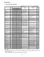


CHAPTER 8. MAINTENANCE
81
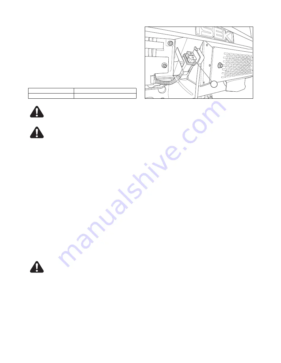
The slow-blow fuse box,2 is located at left side of
radiator.
IMPORTANT:
・
When a fuse or a slow-blow fuse is blown, be sure to
locate the trouble and correct it. When the cause is
not clear, consult your dealer.
・
Be sure to use specified fuses. Larger-capacity fuses
will cause burn-out of electric accessories and wiring.
・
When a slow-blow fuse has been blown out, use
genuine slow-blow fuse.
Slow - blow fuse
Parts code
40A
1650-650-222-00
WARNING:
・
Damaged wire covers should be mended
with insulation tape immediately.
CAUTION:
・
The wiring of the front mower should be
checked every year at your dealer to avoid
electrical fires.
・
Grass and dust around the battery, wiring,
muffler and engine should be removed.
Otherwise they may catch fire.
IMPORTANT:
・
When a wire harness has come off its clamp, it should
be re-clamped immediately.
32. HYDRAULIC SYSTEM PARTS
When hydraulic system parts such as the HST unit,
hydraulic pump, control valve, hydraulic cylinder, piping,
etc. are required to be adjusted or repaired, consult your
ISEKI dealers. Users are advised not to adjust or repair
hydraulic system parts by themselves.
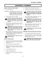
33. SAFETY SWITCHES (SFH240F-B)
Safety devices are installed for safe operation. Make
sure that each device works properly before operation
following the next procedures.
CAUTION:When the engine does not start
due to a defective safety switch or does
not stop when the operator has left the
operator's seat, consult your dealer without
fail.
INSPECTION
1
a. Be seated in the operator's seat.
b. Shift the side PTO lever to the OFF (
N
) position.
c. Shift the center PTO lever to the OFF (
N
) position.
d.
Turn the key switch to the START (
c
) position
without depressing the master brake pedal.
Make sure that the engine is not cranked.
INSPECTION
2
a. Be seated in the operator's seat.
b. Shift the side PTO lever to the ON (
M
) position.
c. Shift the center PTO lever to the OFF (
N
) position.
d. Depress the master brake pedal fully.
e. Turn the key switch to the START (
c
) position.
Make sure that the engine is not cranked.
INSPECTION
3
a. Be seated in the operator's seat.
b. Shift the side PTO lever to the OFF (
N
) position.
c. Shift the centre PTO lever to the ON (
M
) position.
d. Depress the master brake pedal fully.
e. Turn the key switch to the START (
c
) position.
Make sure that the engine is not cranked.
FIG. 131
2
(2) Slow-blow fuse box
Содержание SBC550FH
Страница 1: ...SFH240 SFH220 SCMA48F SCMA54F SMM54F SBC550FL SBC550FH MODELS I S E K I F R O N T M O W E R S ...
Страница 33: ...SFH220 240 32 ...
Страница 34: ...ISEKI FRONT MOWERS FRONT MOWER SECTION ...
Страница 35: ......
Страница 92: ...WIRING HARNESS CABLE 91 WIRING HARNESS CABLE Exept G type ...
Страница 93: ...SFH220 240 92 G type ...
Страница 94: ...ISEKI FRONT MOWERS MOWER DECK SECTION SCMA54F SCMA48F SMM54F SSM54F SFH240F B SFH240F SFH220T ...
Страница 95: ......
Страница 138: ...ISEKI FRONT MOWERS COLLECTOR SECTION ...
Страница 139: ......
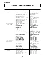
Страница 150: ...CHAPTER 6 TROUBLESHOOTING 149 ...
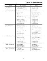
Страница 151: ...SFH220 240 150 ...


