S p e z i a l e l e k t r o n i k G m b H
iseg Spezialelektronik GmbH
Email: [email protected]
Tel ++ 49 (0) 351 / 26 996 - 0
Bautzner Landstr. 23
http://www.iseg-hv.de
Fax ++ 49 (0) 351 / 26 996 - 21
D - 01454 Radeberg/ Rossendorf
25
5.4
Description of the Analogue I/O interface (AIO)
Warning!
Turn off the device with mains switch before connecting/disconnecting the interface cable.
All analogue and digital inputs and outputs are electrically isolated from the protective ground. The
user is responsible that no danger will occur due to a voltage between the AIO and the protective
ground!
“AIF” has to be set in menu “F07 Set Interfce“.
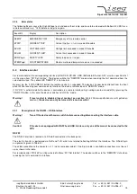
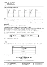
All control inputs and outputs are located at the male D Sub 9 connector labelled “AIO” on the back side of the device. The pin
assignment of this connector is described in the following table.
Table 5.4: Pin assignment male D Sub 9 connector
AIO, male D Sub 9 connector
Pin 1
GND
Return of pins 2-9
Pin 2
V
mon_I
(0 .. 5 V )
Monitor output current
Pin 3
INHIBIT
Digital input signal
Pin 4
V
set_i
(0 .. 5 V)
Set value output current
Pin 5
CC
Digital output signal
Pin 6
GND
Return of pins 2-9
Pin 7
V
mon_v
(0 .. 5 V )
Monitor output voltage
Pin 8
V
set_v
(0 .. 5 V )
Set value output voltage
Pin 9
V
ref
5 V
Reference (1 mA)
5.4.1
Set values
A voltage between 0 - 5 V at Pin 8 (reference potential Pin 6) of the connector “AIO” controls the output voltage between
0 – V
nom
. Similarly, at Pin 4 the output current is controlled between 0 - I
nom
.
5.4.2
Monitor voltages
Monitor voltages (0 - 5 V) proportional to the output voltage and output current are available at Pin 7 and Pin 2 of the connector
“AIO”, respectively (reference potential Pin 6).
5.4.3
INHIBIT
By applying a low level signal at pin 3 of the connector “AIO“, the high voltage generation will be shut off immediately and will
be blocked. High voltage generation is activated with a high level signal or open contact at pin 3 of the connector “AIO“.
Warning!
Do not use the INHIBIT function as a safety loop.
5.4.4
CC
A low level signal at pin 5 of the connector “AIO” indicates, that the device operates in the mode constant current control CC.
On the contrary, a high level signal at this pin indicates, that the device operates in the mode constant voltage control CV.
5.4.5
Function “Auto AIF“
If the interface “AIF” is selected in the menu “F07 Set Interfce“, the automatic function “Auto AIF” in the menu „F06 Auto AIF“
can be enabled. Now the generation of high voltage will start with a rising edge of the INHIBIT function. (without pushing the
button “HV ON”).
If another interface is chosen, the function “Auto AIF” will be disabled automatically.

