


S p e z i a l e l e k t r o n i k G m b H
iseg Spezialelektronik GmbH
Email: [email protected]
Tel ++ 49 (0) 351 / 26 996 - 0
Bautzner Landstr. 23
http://www.iseg-hv.de
Fax ++ 49 (0) 351 / 26 996 - 21
D - 01454 Radeberg/ Rossendorf
21
5.3.3
Description of the IEEE-488 Interface (GPIB)
Warning!
Turn off the device with mains switch before connecting/disconnecting the interface cable.
IEEE-488 interface
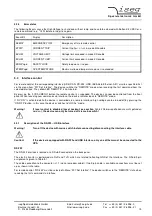
The IEEE-488 bus interface was implemented with a NEC 7210 compatible IEEE controller. The following interface functions
according to IEC 625 are available:
SH1
Source Handshake:
all functions (no polling)
AH1
Acceptor Handshake:
all functions (no polling)
T6
Talker:
s
tandard equipment
L4
Listener:
s
tandard equipment
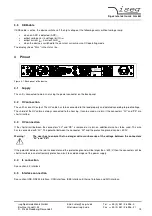
To connect the device to the IEEE bus, a Micro-D25 male connector is located on the back panel. An adapter cable with a 24
pin connector following IEEE-488.2 standard is available as an option.
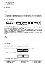
At devices with a Front panel, “IEEE” must be selected at menu “F09 Set Interfce“ for remote control. At devices without a
Front panel, the interface is active after start up.
The IEEE address (1…30) can be specified in the menu “F11 Addr IEEE“. The factory setting for the IEEE address is 17. The
IEEE address can also be changed with the SCPI command :CONFIGURE:GPIB:ADDRESS. When receiving control com-
mands over IEEE, the device switches to “REMOTE” state.
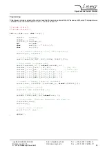
Programming
The command transfer uses ASCII codes. Commands are terminated by <CR><LF> ($0D $0A or 13 10). Alternatively, the
control line EOI (End or Identify) can be set together with the command’s last character. On input side, no leading zeros are
required. The output is in a fixed format without leading zeros.
A minimum time delay of 5 ms between two IEEE commands is needed.
5.3.4
Ethernet Interface
Warning!
Turn off the device with mains switch before connecting/disconnecting the interface cable.
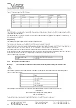
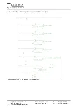
The Ethernet Interface with 10-MBit/s, Full-Duplex, is connected via RJ-45 socket on the device rear.
The device can be connected to a switch via patch cable. If it shall be connected to a PC directly, a crossover cable has to
be used.
“Ethernet” has to be set in menu “F07 Set Interfce“. The additional settings (IP address, net-mask, default gateway) have to
be made with the SCPI Instruction set with EDCP. This can be done over Ethernet or RS-232. Ex works settings are as fol-
lows:
IP-address:
192.168.16.13
Net mask:
255.255.255.0
Default Gateway:
192.168.16.1
Command port:
10001 (fixed)
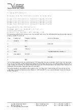
The connection can be tested with the ping command (Start programs accessories command).


